PAGE 4 BRUNSWICK INSTALLATION MANUAL
BLACK WOLF
BASE FRAME AND LEG ASSEMBLY
(CONTINUED)
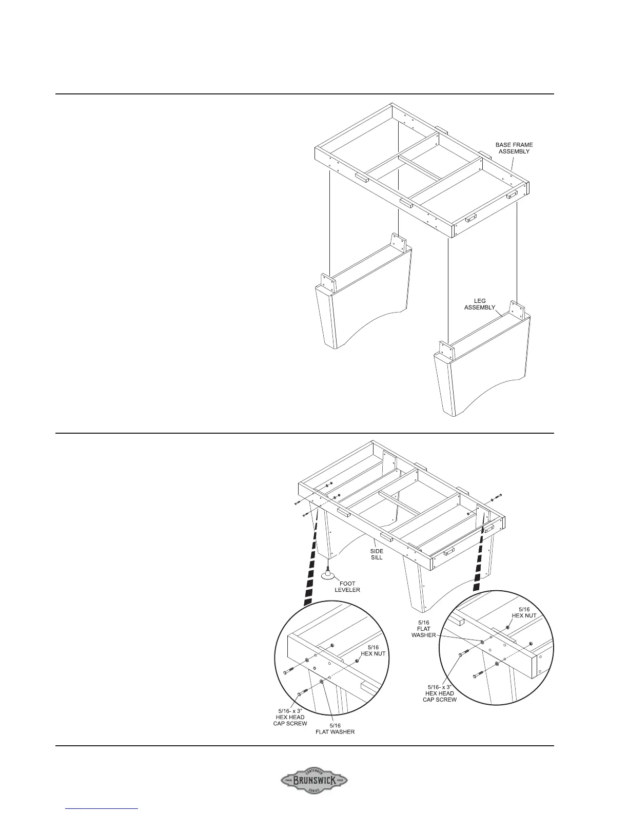
FIGURE THREE
Step #5: Position the two leg assemblies approximately
the length of the base frame.
Step #7: Carefully lower the base frame over the legs.
FIGURE THREE
FIGURE FOUR
Step #8: Align the clearance holes in the leg posts with
the clearance holes in the side sills and attach securely
with 5/16-18 x 3” hex head cap screws, hex nuts and
flatwashers
Step #9: Securely tighten all base frame hardware,
making sure that all top surfaces are flush.
Step #10: Thread a foot leveler into the bottom of each
leg foot.
Step #11: Thread each foot leveler in completely.
Step #12: With table in its permanent location, use a
precision level, to locate the highest corner of the base
frame. Level the table by adjusting the other three
levelers as required.
FIGURE FOUR