Installation
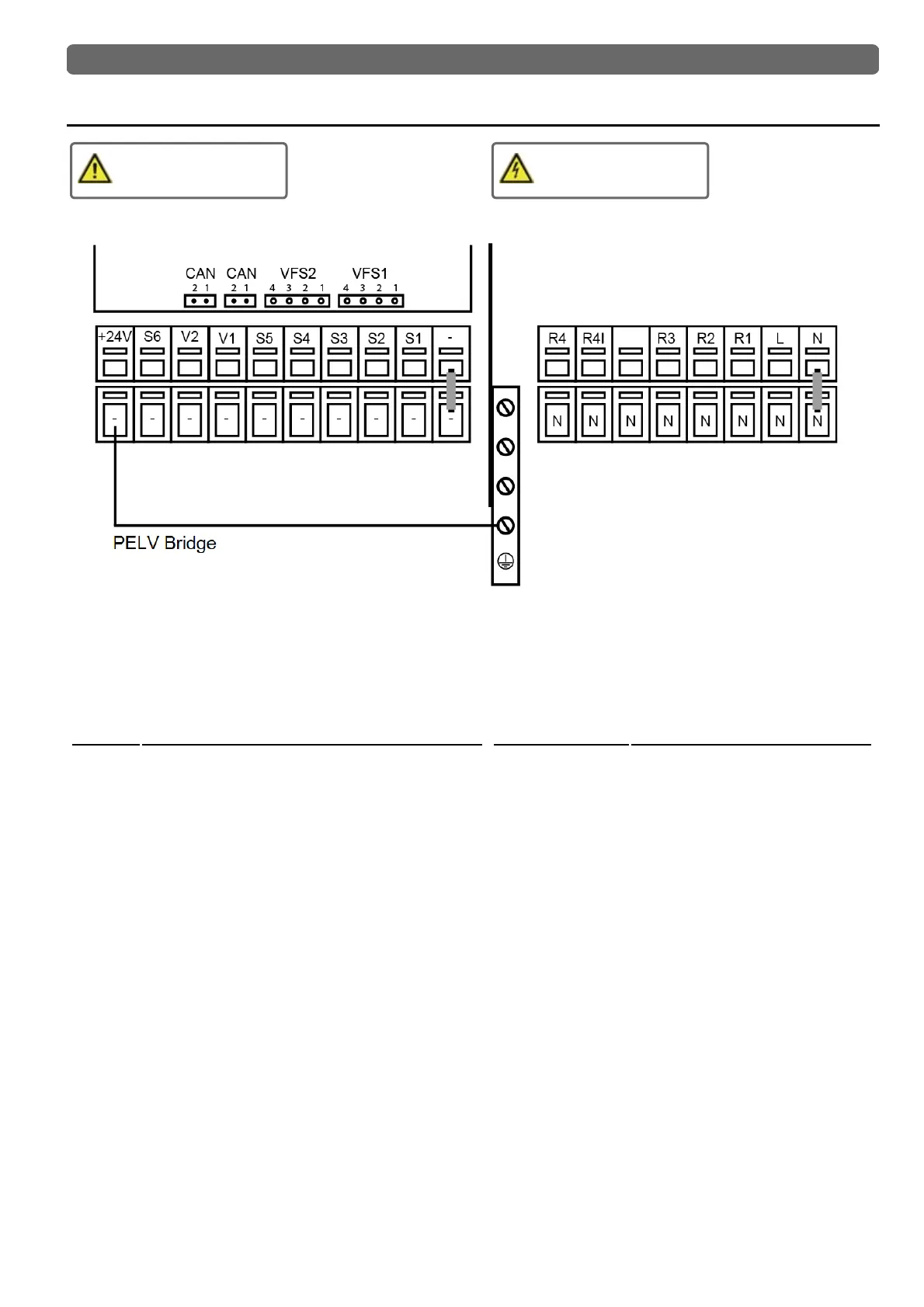
Electrical Terminals
Low voltage
max. 24 VAC / DC
Mains voltages
230 VAC 50 - 60 Hz
On the control board
VFS1 Grundfos Direct Sensor
VFS2 Grundfos Direct Sensor
CAN CAN bus connection (1=high,2=low)
CAN CAN bus connection (1=high,2=low)
Terminal: Connection for:
- GND bridge on the lower ground terminal block
S1 Temperature Sensor 1
S2 Temperature Sensor 2
S3 Temperature Sensor 3
S4 Temperature Sensor 4
S5 Temperature Sensor 5
V1 0-10V / PWM signal output e.g. for controlling high-
efficiency pumps
V2 0-10V / PWM signal output e.g. for controlling high-
efficiency pumps
S6 Temperature Sensor 6 (outdoor)
+ 24V Power supply
The connection of the ground wire is made at the lower gray ter-
minal block.
Terminal: Connection for:
N Neutral conductor N
L Network outer conductor L
R1 Relays 1
R2 Relays 2
R3 Relays 3
R4| Relay 4 | (potential-free contact)
R4 Relay 4 (potential-free contact)
The neutral conductor N must be connected to the N ter-
minal block.
The PE protective conductor must be connected to the PE
metal terminal block!
For high-efficiency pumps with 0-10V / PWM signal input,
the power can be provided (V1 / V2 parallel operation)
over a free relay.
7