Wall Installation
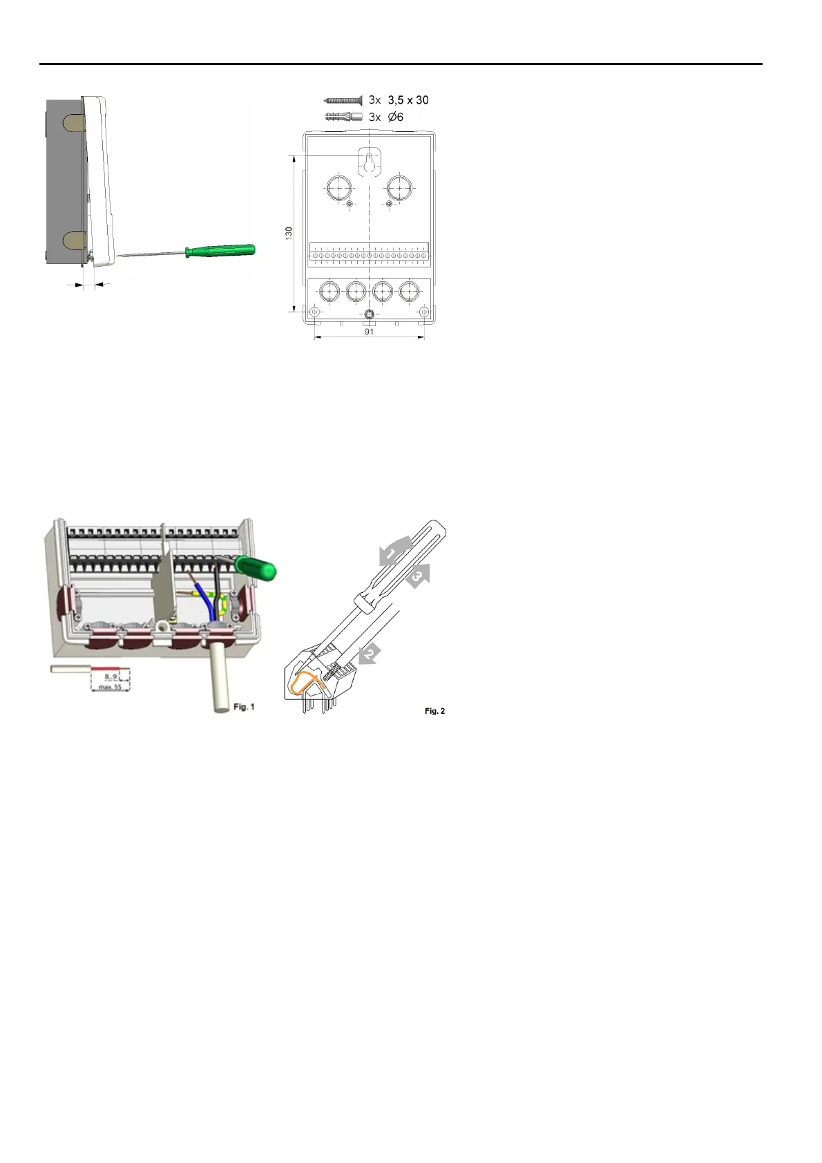
1. Unscrew cover screw completely.
2. Carefully pull upper part of housing
from lower part. During the removal,
the brackets are released as well.
3. Set upper part of housing aside Do not
touch the electronics.
4. Hold the lower part of the housing up
to the selected position and mark the
three mounting holes. Make sure that
the wall surface is as even as possible
so that the housing does not become
distorted when screwed on.
5. Using a drill and size 6 bit, drill three
holes at the points marked on the wall
and push in the plugs.
6. Insert the upper screw and screw it in
slightly.
7. Fit the upper part of the housing and
insert the other two screws.
8. Align the housing and tighten the three
screws.
1. open terminal cover.
2. Strip lines a max. of 55 mm, assemble
the strain reliefs, strip wire ends 8-9
mm (figure 1)
3. Open clamps with a fitting screwdriver
(figure 2) and connect electrical system
to the controller.
4. Suspend clip room cover again and
close with the screw.
5. Turn on mains supply and operate the
controller.
8