Do you have a question about the Bryant 246 and is the answer not in the manual?
Check required packages and rating plate for accuracy.
Central location, firm noncombustible level foundation required.
Air supply requirements for combustion and ventilation, including unconfined and confined spaces.
Step-by-step guide for assembling boiler sections.
Installation of steam risers for specific boiler sizes.
Assembling the manifold and pilot header.
Steps for installing the boiler casing panels.
Components for steam controls and their installation.
Components for water controls and their installation.
Explanation of the gas pressure regulator's function and adjustment.
Details on D2 and D5 gas controls and their thermocouple elements.
Recommendations for gas piping installation and joint compound.
Standard practices for installing flue pipe and venting.
Procedure for lighting D4 and D6 pilot burners.
Procedure for lighting D2 and D5 pilot burners.
Identifying and remedying impurities in boiler water.
Procedures for cleaning steam boilers, including skimming.
Steps for cleaning the boiler's flue passages and bottom.
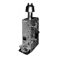
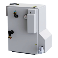
The Bryant Model 246 is a low-pressure, cast-iron sectional boiler designed for use in water or steam heating systems. It is certified by the American Gas Association for use with natural or propane gas. The Type S boiler is suitable for steam systems with a maximum working pressure of 15 psig, while the Type W boiler is for water systems with a normal working pressure of 30 psig, and can be adapted for systems with working pressures of 50 psig or 100 psig with appropriate gauge and relief controls.
The boiler's input and output ratings vary significantly by size, ranging from a 4-section boiler with an input of 315,000 Btuh and a gross steam output of 1,050 sq ft, to a 33-section boiler with an input of 3,360,000 Btuh and a gross steam output of 11,200 sq ft. Water capacities also vary, from 27.3 gallons for the smallest unit to 219.3 gallons for the largest. These ratings are for sea level to 2,000 feet, with a 4% reduction for every 1,000 feet above 2,000 feet. The units can be twinned, back-to-back, to provide up to 6,720,000 Btuh input.
Dimensional data, including width, cover to center of controls, distance between flue centers, and gas connection sizes, are provided in Table I. Supply tappings are 4-inch for 2 to 4 sections (steam) and 2 to 4 sections (water), 4-inch for 3 to 4 sections (steam) and 4 to 19 sections (water), and 4-inch for 4 sections (steam) and 21 to 33 sections (water). Return tappings are 2 @ 4-inches on all sizes.
The boiler is shipped knocked down and requires assembly. It is crucial to read the instructions completely before beginning installation. The boiler should be centrally located with respect to the distribution system and as close to the chimney as possible. It is not intended for use on combustible floors and requires a firm, noncombustible, level foundation. If used as a steam boiler and connected to another, their factory design waterlines must be at equal distance above floor level.
Combustion air requirements depend on the space. In unconfined spaces, normal infiltration is usually adequate. In unusually tight unconfined spaces, a permanent opening of at least one square inch per 5,000 Btuh of total input rating is required, communicating with the outdoors. For confined spaces, two permanent openings (one near the top, one near the bottom) are needed, each with a free area of not less than one square inch per 1,000 Btuh of total input rating, communicating with interior areas that have adequate infiltration from outside. Ducts used for makeup air must have the same cross-sectional area as the openings. Minimum clearance from combustibles is 6 inches on all sides, including the top and draft diverter. A minimum clearance of 24 inches is recommended in front and on the control end for servicing.
Assembly involves fastening base sections together, installing end closing plates, and assembling boiler sections using pull-up tools. Steam risers are required for larger boilers (21-29 sections need one, 31-33 sections need two). A hydrostatic test must be performed to check for water leaks before continuing assembly.
The draft hood comes pre-assembled and is mounted on top of the boiler section with putty to ensure a tight seal. The manifold and pilot header assembly involves installing nipples, elbows, and dresser couplings according to detailed charts for natural gas and propane. Pilot headers connect individual pilots to a tube header, with specific tube sizes for propane and natural gas.
Casing panels are installed by placing them under the draft diverter baffle flange and into rear casing supports, then securing them with screws. The rating plate and water line plate (for steam boilers) are also installed.
Boiler piping for water or steam lines requires specific attention. Returns must be piped to both ends of the boiler. Minimum steam header proportions are specified, and a skimmer tee should be added. A shutoff or steam valve must never be installed between the pressure relief valve and the boiler. The pressure relief valve's discharge capacity must equal the boiler's output in pounds per hour.
Steam controls include a low-water cutoff, high-pressure limit control, compound pressure-vacuum gauge, water gauge glass set, siphon, and a 15-psig pressure relief valve. Water controls include a water temperature high-limit control, combination temperature-pressure-altitude gauge, and a pressure relief valve.
Gas controls vary by model and gas type. D2 and D5 controls use thermocouple pilots, while D6 controls use a thermopile pilot. The pilot flame must properly surround the thermocouple/thermopile to generate the necessary electrical current for valve operation. Gas piping must follow local codes and ordinances, using ground-joint-type unions and pipe dope resistant to propane. A main manual gas shutoff valve should be mounted approximately 5 feet above floor level, with a tapping for a manual pilot gas shutoff valve on the inlet side. Escapement tubes from the gas valve are installed on the pilot burner in the base closest to the control end.
Electrical wiring must comply with the National Electric Code and local requirements. A Class 2 transformer is required for control wiring, except for D6 millivolt natural gas controls.
Flue connection and venting require consulting dimensional drawings and AGA Standards for chimney connections. A minimum upward slope of 1/4 inch per linear foot from boiler to chimney is required. Flue pipe should be run as directly as possible, keeping turns to a minimum, and inserted into the chimney without extending beyond the inside wall. It should not connect to a chimney serving an open fireplace and must be insulated where it passes near combustible material. Chimneys should extend at least 2 feet above any object within a 15-foot radius. A simple vent system requires a 6-foot minimum vertical rise immediately off the draft hood, terminating above the roof with a suitable rain cap. For multiple-base boilers, a pant leg venting system may be used.
After all gas connections are made, check for leaks with a soap-and-water solution. The supply lines must be purged to eliminate trapped air.
Gas pressure regulator adjustment involves turning the adjusting screw clockwise to increase input and counter-clockwise to decrease input. Manifold pressure for natural gas should be 3 inches wc, and for propane gas, 11 inches wc. If the measured input varies significantly from rated input, orifices should be changed.
Burner adjustment involves allowing the boiler to operate for at least 15 minutes, then adjusting the primary air shutter until the yellow tip disappears from the flame.
Flue connections to the chimney should be inspected annually for good condition and obstructions.
Boilers should generally not be drained unless absolutely necessary. Water should remain in the boiler between heating seasons. If makeup water is added, trapped air should be removed through system vents. Keeping pilots lighted during summer months can reduce surface corrosion. Frequent water additions shorten boiler life; all leaks should be repaired. Boiler water should be mildly alkaline (pH 7-8).
Manually trip the relief valve once a month to ensure proper opening and seating. Never plug a continually leaking valve.
Cleaning steam boilers involves skimming off impurities by running a temporary connection from the skimmer tee to a drain. With the boiler empty and cool, slowly add water, keeping the main gas burners off, and adjust the flame at the main manual shutoff valve to keep the water just below boiling point. Skim until no trace of impurities remains. Water can be checked for oil by boiling a sample. For sediment, "blowing down" the boiler is necessary. This involves filling the boiler, building up 5 pounds of steam pressure, then draining the entire contents through a drain valve on the opposite end from the feed water inlet. This process should be repeated until the blow-off water is clear.
If excessive dirt or sludge is present, a boiler cleaning compound from a reputable manufacturer can be used according to instructions. All traces of the compound must be thoroughly flushed out. Sal Soda (washing soda) can be used for exceptionally dirty boilers but requires extreme caution due to potential harm if not thoroughly washed out, ensuring the water pH does not exceed 7-8. A solution of one pound of Sal Soda dissolved in hot water per 10 gallons of boiler water can be poured into a convenient opening. The fire is then adjusted to maintain simmering for 5-6 hours, then increased to build 5-pounds pressure, and the boiler is "blown down." This process is repeated until the boiler is free of soda, and fresh, clear water is added to the proper level, ensuring the pH value is between 7 and 8.
The flue passages between sections should be examined yearly and cleaned with a wire flue brush. This involves turning off electrical power and gas supply, removing front casing panels, burner doors, burners, and top cover from the draft hood, cleaning the flue passages and boiler bottom, then reassembling.