If a factory-supplied external Filter/Media cabinet is provided,
instructions for its application, assembly, and installation are
packaged with the cabinet. The Filter/Media cabinet can be used
with the factory-supplied washable filter or a factory-specified
high-efficiency disposable filter (see cabinet instructions).
If installing the filter in the furnace blower compartment, deter-
mine location for filter and relocate filter retaining wire if
necessary. See Table 2 to determine correct filter size for desired
filter location. Table 2 indicates filter size, location, and quantity
shipped with this furnace. See Fig. 2 for location and size of
bottom and side return-air openings.
CAUTION: Use care when cutting support rods in filters
to protect against flying pieces and sharp rod ends. Wear
safety glasses, gloves, and appropriate protective cloth-
ing. Failure to follow this caution could result in personal
injury.
CAUTION: For airflow requirements above 1800 CFM,
see Air Delivery table in Product Data literature for
specific use of single side inlets. The use of both side
inlets, a combination of 1 side and the bottom, or the
bottom only will ensure adequate return air openings for
airflow requirements above 1800 CFM.
NOTE: Side return-air openings can ONLY be used in UPFLOW
configurations. Install filter(s) as shown in Fig. 18. Bottom
return-air opening may be used with all 4 orientations. Filter may
need to be cut to fit some furnace widths. Install filter as shown in
Fig. 19.
NOTE: Remove and discard bottom closure panel when bottom
inlet is used.
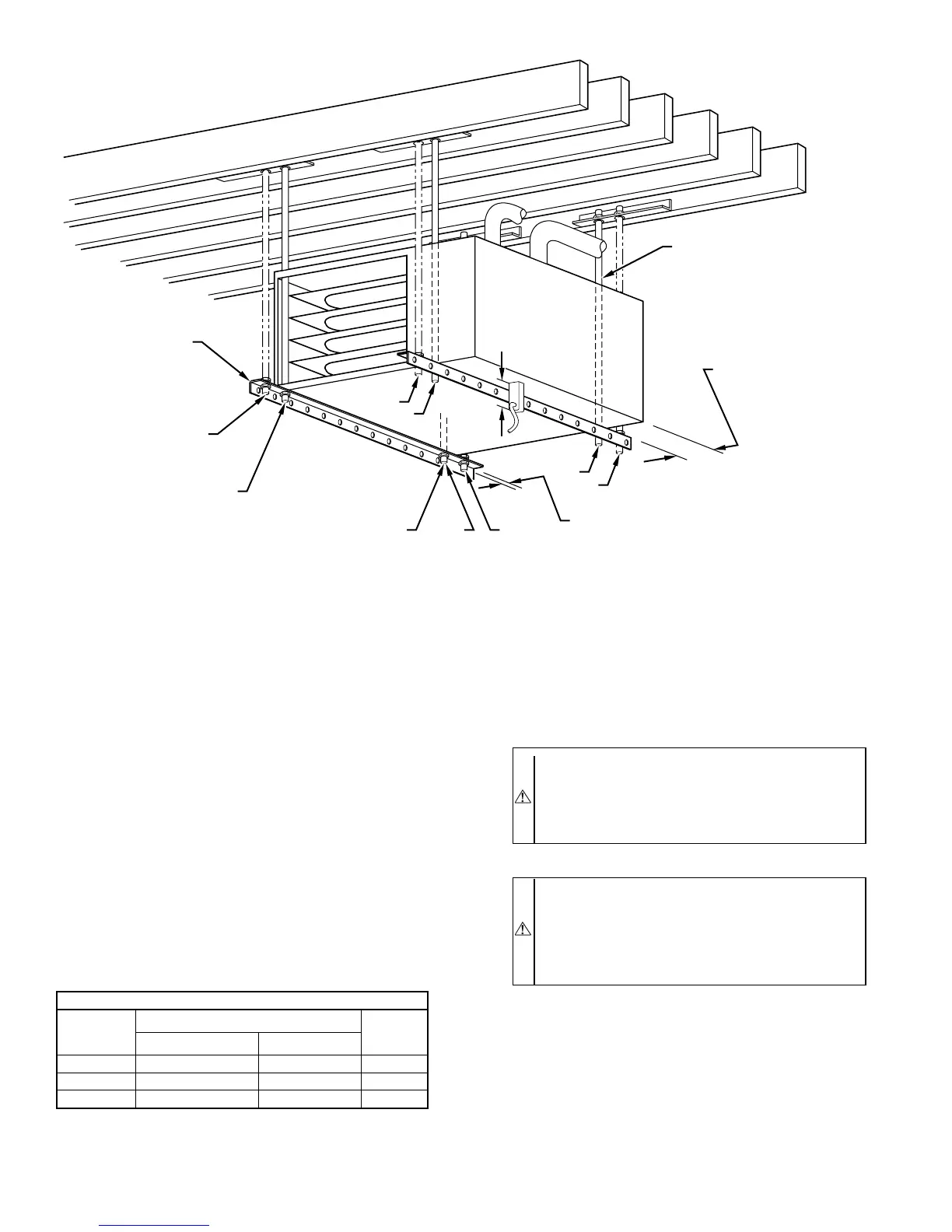
Fig. 17—Crawlspace Horizontal Application
A93304
NOTES:
ANGLE
IRON OR
EQUIVALENT
(B)
(A) ROD LOCATION
USING DIMPLE
LOCATORS
(SEE DIMENSIONAL
DWG FOR
LOCATIONS)
13
/16-IN. MAX
ALTERNATE SUPPORT
LOCATION FROM BACK
ALTERNATE SUPPORT
LOCATION 4-IN. MIN
8-IN. MAX
3
⁄8-IN. ROD
(A)
(B)
(A)
(B)
(B)
(A)
1. A 1 In. clearance minimum between top of
furnace and combustible material.
2. The entire length of furnace must be
supported when furnace is used in horizontal
position to ensure proper drainage.
(A) PREFERRED ROD LOCATION
(B) ALTERNATE ROD LOCATION
DRAIN
5
3
⁄
4
″
3
/8-IN. HEX NUT
& WASHER (4)
REQD PER ROD
TABLE 2—FILTER INFORMATION
AIR FILTER LOCATED IN BLOWER COMPARTMENT
FURNACE
CASING
WIDTH (IN.)
FILTER SIZE (IN.)*
FILTER
TYPE
Side Return Bottom Return
17–1/2 (1)16X25X1† (1)16X25X1† Cleanable
21 (1)16X25X1 (1)20X25X1† Cleanable
24–1/2 (1or2)16X25X1 (1)24X25X1† Cleanable
* Filters may be field modified by cutting filter material and support rods (3) in
filters. Alternate sizes and additional filters may be ordered from your dealer.
† Factory-provided with furnace.
—16—
→
→
 Loading...


