5. When above items have been completed, the component
test sequence will occur as described in the Component Test
Sequence section above.
NOTE: Be sure to record the status code which is flashed 4 times
at start of component test for further troubleshooting.
6. After component testis completed and LED is ON continu-
ously indicating the furnace is ready to operate when a
signal from the thermostat is received, replace main furnace
door.
INITIATING COMPONENT TEST BY JUMPERING CON-
TROL TEST TERMINAL
1. Remove main furnace door.
2. Remove blower access panel.
3. Manually close blower access panel door switch. Use
apiece of tape to hold switch closed.
WARNING: Blower access panel door switch opens
115-v power to control center. No component operation
can occur. Caution must be taken when manually closing
this switch for service purposes. Failure to follow this
warning could result in electrical shock, personal injury,
or death.
4. BRIEFLY short (jumper) TEST, 1/4-in. quick-connect
terminal on control center (adjacent to the LED diagnostic
light) and the C
OM terminal on thermostat connection block.
(See Fig. 25.)
NOTE: If TEST to C
OM terminals are jumpered longer than 2 sec,
LED will flash rapidly, and retrieval request will be ignored.
5. When above items have been completed, the component
test sequence will occur as described in the Component Test
Sequence section above.
NOTE: Be sure to record the status code which is flashed 4 times
at start of component test for further troubleshooting.
6. After component test is completed and furnace is operating
properly, release blower access panel door switch, replace
blower access panel, and replace main furnace door.
START-UP PROCEDURES
I. GENERAL
1. Furnace must have a 115-v power supply properly con-
nected and grounded. Proper polarity must be maintained
for correct operation.
NOTE: Proper polarity must be maintained for 115-v wiring. If
polarity is incorrect, control center LED status indicator light will
flash rapidly and furnace will not operate.
2. Thermostat wire connections at terminals R, W, G, and Y
must be made at 24-v terminal block on control center.
3. Natural gas service pressure must not exceed 0.5 psig
(14-in. wc), but must be no less than 0.16 psig (4.5-in. wc).
4. Blower access panel must be in place to complete 24-v
electrical circuit to furnace.
CAUTION: These furnaces are equipped with a manual
reset limit switch in burner box. This switch will open if
an overheat condition (rollout) occurs in burner enclo-
sure. Correct inadequate combustion-air supply or im-
proper venting condition and reset switch. DO NOT
jumper this switch.
Before operating furnace, check each manual reset switch for
continuity. If necessary, press button to reset switch.
II. PRIME CONDENSATE TRAP WITH WATER
CAUTION: Condensate trap must be PRIMED or
proper draining may not occur. The condensate trap has 2
internal chambers which can ONLY be primed by pour-
ing water into the inducer drain side of condensate trap.
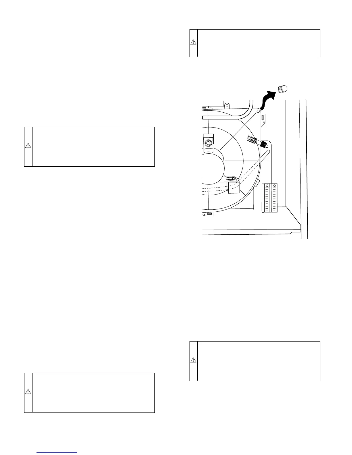
1. Remove upper inducer housing drain connection cap. (See
Fig. 42.)
2. Connect field-supplied 1/2-in. ID tube to upper inducer
housing drain connection.
3. Insert field-supplied funnel into tube.
4. Pour 1 quart of water into funnel/tube. Water should run
through inducer housing, overfill condensate trap, and flow
into open field drain. (See Fig. 43.)
5. Remove funnel and tube from inducer housing and replace
drain connection cap and clamp.
III. PURGE GAS LINES
If not previously done, purge lines after all connections have been
made and check for leaks.
WARNING: Never purge a gas line into a combustion
chamber. Never use matches, candles, flame, or other
sources of ignition for purpose of checking leakage. Use
a soap-and-water solution to check for leakage. Failure to
follow this warning could result in fire, explosion, per-
sonal injury, or death.
IV. ADJUSTMENTS
A. Set Gas Input Rate
Furnace gas input rate on rating plate is for installations at altitudes
up to 2000 ft.
In the U.S.A., the input ratings for altitudes above 2000 ft must be
reduced by 2 percent for each 1000 ft above sea level.
Fig. 42—Inducer Housing Drain Tube
A99118
—34—
 Loading...


