CAN/CGA-B149.1- and .2-M95 National Standard of Canada,
Natural Gas and Propane Installation Codes (NSCNGPIC). Wear
safety glasses and work gloves. Have a fire extinguisher available
during start-up and adjustment procedures and service calls.
Recognize safety information. This is the safety-alert symbol
.
When you see this symbol on the unit and in instructions or
manuals, be alert to the potential for personal injury.
Understand these signal words; DANGER, WARNING, and
CAUTION. These words are used with the safety-alert symbol.
DANGER identifies the most serious hazards which will result in
severe personal injury or death. WARNING signifies hazards
which could result in personal injury or death. CAUTION is used
to identify unsafe practices which would result in minor personal
injury or product and property damage. NOTE is used to highlight
suggestions which will result in enhanced installation, reliability,
or operation
INTRODUCTION
The model 350MAV, Series E and F Furnaces are available in
sizes 40,000 through 138,000 Btuh input capacities.
The 350MAV Multipoise Condensing Gas-Fired Furnaces are
C.S.A. (A.G.A. and C.G.A.). certified for natural and propane
gases and for installation in alcoves, attics, basements, closets,
utility rooms, crawlspaces, and garages. The furnace is factory-
shipped for use with natural gas. A C.S.A. (A.G.A. and C.G.A.)
listed gas conversion kit is required to convert furnace for use with
propane gas. The 350MAV 040 through 120 size units are C.S.A.
(A.G.A. and C.G.A.) approved for use in manufactured (mobile)
homes when factory accessory conversion kit is used. The 140 size
unit is NOT approved for use in manufactured (mobile) homes.
These furnaces are suitable for installation in a residence built on
site or a manufactured residence completed at final site. The design
of this furnace line is NOT A.G.A/C.G.A. certified for installation
in recreation vehicles or outdoors.
These furnaces SHALL NOT be installed directly on carpeting,
tile, or any other combustible material other than wood flooring. In
downflow installations, factory accessory floor base MUST be
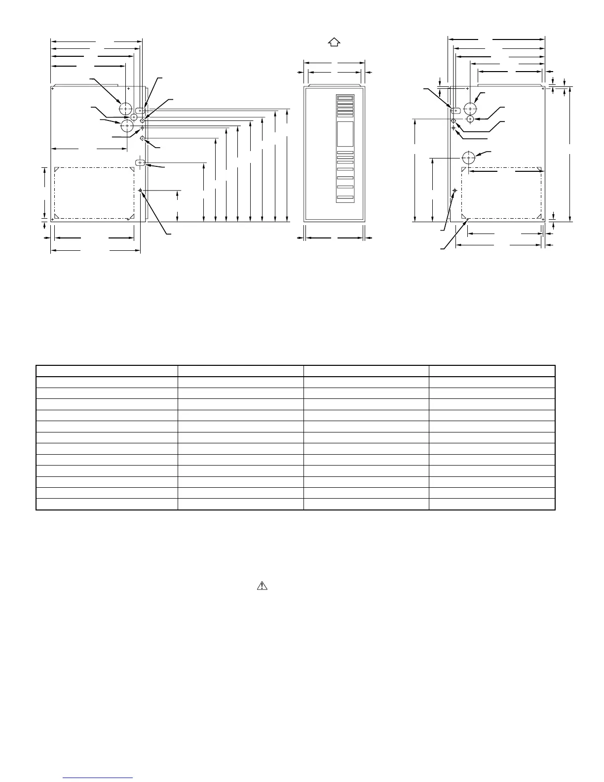
Fig. 2—Dimensional Drawing
DIMENSIONS (IN.)
UNIT SIZE A D E
040-08 17-1/2 15-7/8 16
040-12 17-1/2 15-7/8 16
060-08 17-1/2 15-7/8 16
060-12 17-1/2 15-7/8 16
060-16 17-1/2 15-7/8 16
080-12 17-1/2 15-7/8 16
080-16 17-1/2 15-7/8 16
080-20 21 19-3/8 19-1/2
100-16 21 19-3/8 19-1/2
100-20 21 19-3/8 19-1/2
120-20 24-1/2 22-7/8 23
140-20 24-1/2 22-7/8 23
A99111
17
5
⁄
16
"
24
1
⁄
2
"
27
9
⁄
16
"
TYP
27
5
⁄
8
"
29
11
⁄
16
"
TYP
30
13
⁄
16
"
32
5
⁄
8
"
TYP
33
1
⁄
4
"
TYP
CONDENSATE
DRAIN TRAP
LOCATION
(ALTERNATE
UPFLOW)
7
⁄8-IN. DIA
ACCESSORY
POWER ENTRY
7
⁄8-IN. DIA
POWER CONN
CONDENSATE DRAIN
TRAP LOCATION
(DOWNFLOW &
HORIZONTAL LEFT)
26
15
⁄
16
"
24
1
⁄
2
"
22
5
⁄
16
"
2
-IN. COMBUSTION-
AIR CONN
1
⁄
2
-IN. DIA
GAS CONN
2
-IN. VENT CONN
1
⁄2-IN. DIA THERMOSTAT
ENTRY
22
11
⁄
16
"
SIDE INLET
23
1
⁄
4
" TYP
SIDE INLET
1
1
⁄
4
"
1" E
INLET
11
⁄
16
"
11
⁄
16
"
D
13
⁄
16
"
13
⁄
16
"
OUTLET
A
AIRFLOW
OUTLET
26
15
⁄
16
"
28
1
⁄
2
"
22
5
⁄
16
"
19"
13
⁄
16
"
5
⁄
8
"
5
⁄
16
"
1"
39
7
⁄
8
"
22
1
⁄
4
" TYP
11
⁄
16
"
7
⁄
16
"
24
3
⁄
16
"
BOTTOM INLET
18
1
⁄
4
"
22
11
⁄
16
"
CONDENSATE DRAIN
TRAP LOCATION
(DOWNFLOW &
HORIZONTAL RIGHT)
OR ALTERNATE
1
⁄
2
-IN. DIA GAS CONN
2-IN. COMBUSTION-
AIR CONN
1
⁄2-IN. DIA
GAS CONN
7
⁄8-IN. DIA
POWER CONN
1
⁄2-IN. DIA
THERMOSTAT ENTRY
2-IN. VENT CONN
DIMPLE LOCATORS
FOR HORIZONTAL
HANGING
14
1
⁄
2
"
TYP
SIDE INLET
NOTES: 1. Minimum return-air openings at furnace, based on metal duct. If flex duct is used,
see flex duct manufacturer’s recommendations for equivalent diameters.
2. Minimum return-air opening at furnace:
a. For 800 CFM–16-in. round or 14
1
/
2
x 12-in. rectangle.
b. For 1200 CFM–20-in. round or 14
1
/
2
x 19
1
/
2
-in. rectangle.
c. For 1600 CFM–22-in. round or 14
1
/
2
x 23
1
/
4
-in. rectangle.
d. For airflow requirements above 1800 CFM, see Air Delivery table in Product Data
literature for specific use of single side inlets. The use of both side inlets, a
combination of 1 side and the bottom, or the bottom only will ensure adequate
return air openings for airflow requirements above 1800 CFM.
9
7
⁄
16
"
TYP
26
15
⁄
16
" TYP
CONDENSATE
DRAIN LOCATION
(UPFLOW)
30
1
⁄
2
"
9
⁄
16
"
TYP
CONDENSATE
DRAIN LOCATION
(UPFLOW)
26
1
⁄
4
"
26
1
⁄
4
"
—2—