WARNING: Caution should be taken to prevent drain-
ing where slippery conditions may cause personal inju-
ries. Excessive condensate draining may cause saturated
soil conditions which may result in damage to plants.
C. CONDENSATION DRAIN PROTECTION
Freezing condensate left in condensate trap and drain line may
cause cracks, and possible water damage may occur. If freeze
protection is required, use condensate freeze protection accessory
or equivalent 3 to 6 watt per ft at 120–v and 40°F self-regulating,
shielded, and waterproof heat tape. See Installation Instructions
supplied with accessory or heat tape manufacturer’s recommenda-
tions.
1. Fold heat tape in half and wrap on itself 3 times.
2. Locate heat tape between sides of condensate trap back.
(See Fig. 41.)
3. Use wire ties to secure heat tape in place. Wire ties can be
positioned in notches of condensate trap sides. (See Fig.
41.)
4. Wrap field drain pipe with remaining heat tape, approxi-
mately 1 wrap per ft.
5. When using field-supplied heat tape, follow heat tape
manufacture’s instructions for all other installation guide-
lines.
XI. SEQUENCE OF OPERATION
CAUTION: Furnace control must be grounded for
proper operation, or control will lock out. Control is
grounded through green wire routed to gas valve and
burner box screw.
Using schematic diagram, follow sequence of operation through
different modes. (See Fig. 24.) Read and follow wiring diagram
carefully.
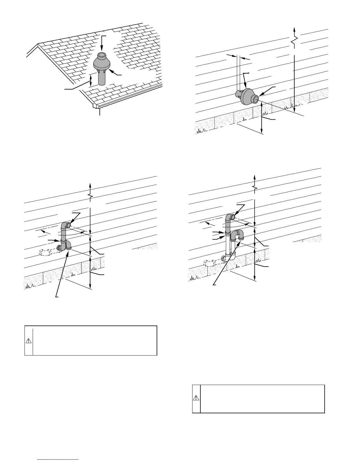
COMBUSTION
AIR
MAINTAIN 12 IN.
(18 IN. FOR CANADA)
MINIMUM CLEARANCE
ABOVE HIGHEST
ANTICIPATED SNOW
LEVEL. MAXIMUM OF
24 IN. ABOVE ROOF.
VENT
A93054
Fig. 31—Concentric Vent and Combustion-Air Roof Termi-
nation (Preferred)
Fig. 33—Sidewall Termination of 12 in. or More
A87225
MAINTAIN 12 IN.
CLEARANCE
ABOVE HIGHEST
ANTICIPATED SNOW
LEVEL OR GRADE,
WHICHEVER IS
GREATER.
90°
VENT
12 IN. SEPARATION
BETWEEN BOTTOM OF
COMBUSTION AIR AND
BOTTOM OF VENT
BRACKET
COMBUSTION-AIR
12″ MINIMUM
OVERHANG OR ROOF
MAINTAIN 12 IN.
CLEARANCE
ABOVE HIGHEST
ANTICIPATED SNOW
LEVEL OR GRADE,
WHICHEVER IS
GREATER.
COMBUSTION-AIR
VENT
1″ MAXIMUM
12″ MINIMUM
OVERHANG OR ROOF
A93055
Fig. 32—Concentric Vent and Combustion-Air Side Termi-
nation
MAINTAIN 12 IN.
CLEARANCE
ABOVE HIGHEST
ANTICIPATED SNOW
LEVEL OR GRADE,
WHICHEVER IS
GREATER.
90°
VENT
12 IN. SEPARATION
BETWEEN BOTTOM OF
COMBUSTION AIR AND
BOTTOM OF VENT
BRACKET
COUPLING
12″ MINIMUM
OVERHANG OR ROOF
COMBUSTION-AIR
(ELBOW PARALLEL
TO WALL)
A87226
Fig. 34—Sidewall Termination of Less than 12 in.
—30—
 Loading...


