NOTE: If 115-v power supply to furnace or blower access panel
switch is interrupted during a call for heat, blower operates for 90
sec when power is restored before heating cycle is resumed.
A. HEATING MODE
When wall thermostat calls for heat, R-W circuit closes. Furnace
control performs a self-check, verifies pressure switch contacts are
open, and starts inducer motor.
1. Prepurge period—As inducer motor comes up to speed,
pressure switch contacts close to begin a 15-sec prepurge
period.
2. Ignitor warm up—At end of prepurge period, ignitor is
energized for a 17-sec ignitor warm-up period.
3. Ignition sequence—When ignitor warm-up period is com-
pleted, gas valve opens, permitting gas flow to burners
TABLE 7—MAXIMUM ALLOWABLE EXPOSED VENT PIPE LENGTH (FT) WITH AND WITHOUT INSULATION IN WINTER
DESIGN TEMPERATURE AMBIENT*
UNIT
SIZE
WINTER DESIGN
TEMPERATURE
(°F)
MAX PIPE
DIAMETER
(IN.)
WITHOUT
INSULATION
WITH 3/8–IN. OR
THICKER INSULATION†
040
20 1.5 51 70
0 1.5 28 70
-20 1.5 16 70
20 2 45 70
0 2 22 70
-20 2 10 58
060
20 2 65 70
0 2 35 70
-20 2 20 70
080
20 2 55 55
0 2 48 55
-20 2 30 55
20 2.5 70 70
0 2.5 47 70
-20 2.5 28 70
100
20 2.5 40 40
0 2.5 40 40
-20 2.5 38 40
20 3 70 70
0 3 50 70
-20 3 28 70
120
20 3 70 70
0 3 61 70
-20 3 37 70
20 4 70 70
0 4 48 70
-20 4 23 70
140
20 3 60 60
0 3 60 60
-20 3 44 60
20 4 70 70
0 4 57 70
-20 4 30 70
* Pipe length (ft) specified for maximum pipe lengths located in unconditioned spaces. Pipes located in unconditioned space cannot exceed total allowable pipe length as
specified in Table 6.
† Insulation thickness based on R value of 3.5 (ft_ •°F• hr)/(Btu•in.)
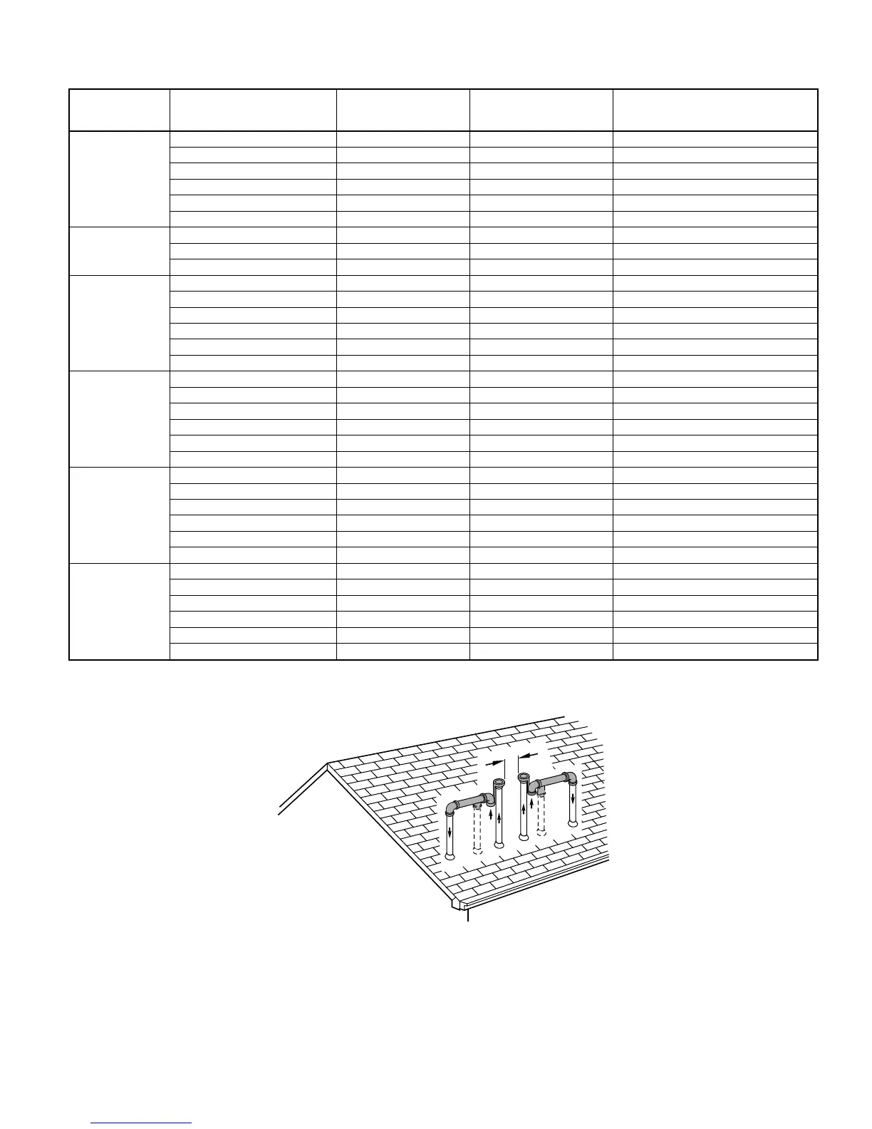
Fig. 35—Rooftop Termination (Dimension “A” is Touching or 2-in. Maximum Separation)
A96128
A
—31—