used when installed on combustible materials and wood flooring.
Special base is not required when this furnace is installed on
manufacturer’s Coil Assembly Part No. CD5 or CK5, or when Coil
Box Part No. KCAKC is used.
These furnaces are shipped with the following materials to assist in
proper furnace installation. These materials are shipped in the main
blower compartment.
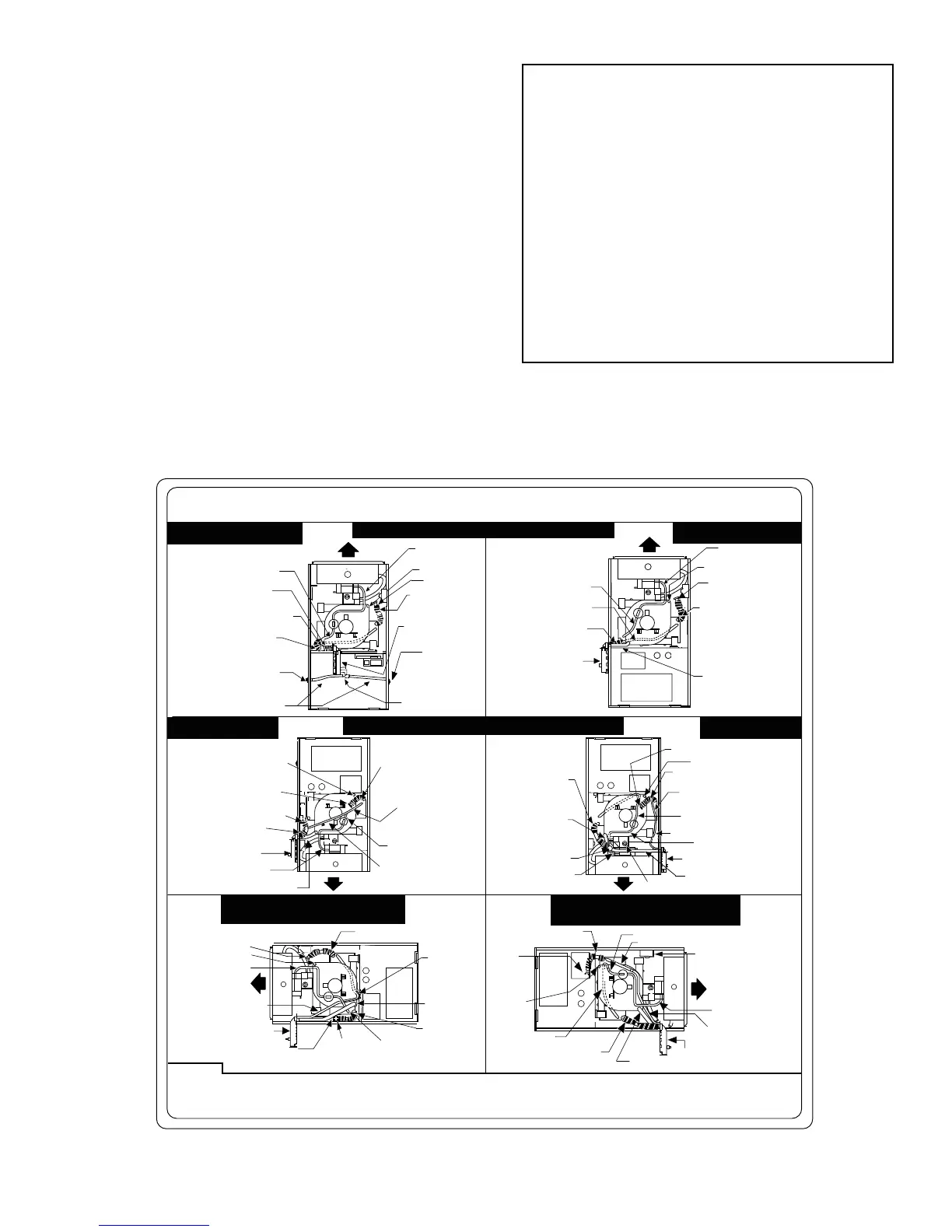
These furnaces are shipped with the drain and pressure tubes
connected for UPFLOW applications. Minor modifications are
required when used in DOWNFLOW, HORIZONTAL RIGHT, or
HORIZONTAL LEFT (supply-air discharge direction) applica-
tions as shown in Fig. 1. See details in Applications section.
This furnace must be installed with a direct-vent (combustion air
and flue) system and a factory accessory termination kit. In a
direct-vent system, all air for combustion is taken directly from the
outside atmosphere and all flue products are discharged to the
outside atmosphere. See furnace and factory accessory termination
kit instructions for proper installation.
Fig. 3—Clearances to Combustibles
A00308
Furnace is shipped from factory in upflow configuration. Pressure tube and drain tube routing MUST match the diagrams below.
Tube location when used in DOWNFLOW application
Tube location when used on
HORIZONTAL - RIGHT application
PLUG
CAP
COLLECTOR BOX DRAIN TUBE
(BLUE & WHITE STRIPED)
COLLECTOR BOX TUBE
(PINK)
COLLECTOR BOX DRAIN TUBE
(BLUE)
INDUCER HOUSING DRAIN TUBE
(VIOLET)
COLLECTOR BOX TUBE
(PINK)
COLLECTOR BOX DRAIN
TUBE
(BLUE & WHITE STRIPED)
COLLECTOR BOX DRAIN TUBE
(BLUE)
INDUCER HOUSING (MOLDED) DRAIN TUBE
(BEHIND COLLECTOR BOX DRAIN TUBE)
FIELD-INSTALLED
FACTORY-SUPPLIED DRAIN TUBE
COUPLING (LEFT DRAIN OPTION)
FIELD-INSTALLED FACTORY-SUPPLIED
DRAIN TUBE
FIELD-INSTALLED
FACTORY-SUPPLIED 1/2-IN.
CPVC STREET ELBOWS (2)
FOR LEFT DRAIN OPTION
COLLECTOR BOX TUBE
(GREEN)
CONDENSATE TRAP
CAP
Condensate Trap; Factory Installed
in Blower Shelf
CONDENSATE TRAP
COLLECTOR BOX TUBE (GREEN)
Condensate Trap on LEFT
Side Optional
CAP
PLUG
COLLECTOR BOX
DRAIN TUBE (BLUE)
PLUGGED END
COLLECTOR BOX DRAIN TUBE
(BLUE & WHITE STRIPED)
COLLECTOR BOX
TUBE (GREEN)
COLLECTOR BOX
TUBE (PINK)
COLLECTOR BOX
EXTENSION TUBE
CONDENSATE TRAP
INDUCER HOUSING DRAIN TUBE (VIOLET)
COLLECTOR BOX
EXTENSION TUBE
COLLECTOR BOX TUBE
(PINK)
COLLECTOR BOX DRAIN TUBE
(BLUE)
COLLECTOR BOX TUBE
(GREEN)
CONDENSATE TRAP
INDUCER HOUSING DRAIN
TUBE (VIOLET)
COLLECTOR BOX EXTENSION TUBE
COLLECTOR BOX DRAIN
TUBE
(BLUE & WHITE STRIPED)
Condensate Trap on
RIGHT Side
COLLECTOR BOX
EXTENSION DRAIN TUBE
DRAIN TUBE COUPLING
GAS VALVE
DRAIN TUBES ROUTED IN
FRONT OF GAS VALVE
PLUG
CAP
COLLECTOR BOX DRAIN TUBE
(BLUE & WHITE STRIPED)
CONDENSATE TRAP
COLLECTOR BOX
EXTENSION TUBE
COLLECTOR BOX
TUBE (GREEN)
INDUCER HOUSING
DRAIN TUBE
(VIOLET)
COLLECTOR BOX TUBE (PINK)
RELOCATE TUBE BETWEEN BLOWER
SHELF AND INDUCER HOUSING FOR
040,060, AND 080 HEATING INPUT
FURNACES
CAP
PLUG
COLLECTOR BOX DRAIN TUBE
(BLUE)
COLLECTOR BOX EXTENSION TUBE
COLLECTOR BOX TUBE (PINK)
COLLECTOR BOX
TUBE (GREEN)
COLLECTOR BOX DRAIN TUBE
(BLUE AND WHITE STRIPED)
INDUCER HOUSING DRAIN TUBE (VIOLET)
CONDENSATE TRAP
Condensate Trap on
LEFT Side
COLLECTOR BOX
DRAIN TUBE (BLUE)
PLUG
Tube location when used in UPFLOW application
Tube location when used on
HORIZONTAL - LEFT application
CAP
PLUG
COLLECTOR BOX
EXTENSION TUBE
DRAIN TUBE
COUPLING
COLLECTOR BOX EXTENSION DRAIN TUBE
(Blower access panel removed)
1. All tubing must be connected securely and routed to avoid kinks and traps.
2. Pressure tubing must always slope away from pressure switch to collector box connection as shown.
3. HORIZONTAL-LEFT installations require the collector box pressure tube to be relocated between the inducer housing and the blower shelf to
prevent a trap.Refer to the Installation Instructions for further details.
NOTE:
324999-201 REV. C
FIELD-INSTALLED
FACTORY-SUPPLIED
DRAIN TUBE COUPLING
(RIGHT DRAIN OPTION)
BURNER ENCLOSURE
PRESSURE REFERENCE
TUBE ASSEMBLY
BURNER ENCLOSURE
PRESSURE REFERENCE
TUBE ASSEMBLY
BURNER ENCLOSURE PRESSURE
REFERENCE TUBE ASSEMBLY
BURNER ENCLOSURE
PRESSURE REFERENCE
TUBE ASSEMBLY
BURNER ENCLOSURE
PRESSURE REFERENCE
TUBE ASSEMBLY
BURNER ENCLOSURE PRESSURE
REFERENCE TUBE ASSEMBLY
TUBE ROUTING
AUXILIARY "J" BOX RELOCATED HERE
Installer Packet includes:
Installation, Startup, and Operating Instructions
Service and Maintenance Instructions
User’s Information Manual
Warranty Certificate
Loose Parts Bag includes Quantity
Pressure tube extension 1
Collector Box or condensate trap extension tube 1
Inducer housing drain tube 1
1/2-in CPVC street elbow 2
Drain tube coupling 1
Drain tube coupling grommet 1
Vent and combustion-air pipe support 2
Condensate trap hole filler plug 3
Vent and combustion-air intake hole filler plug 2
Combustion-air pipe perforated disk assembly 1
Vent Pipe Extension 1*
* ONLY supplied with some furnaces.
—3—