25
Step 5 -- Filter Arrangement
FIRE, CARBON MONOXIDE AND
POISONING HAZARD
Failure to follow this warning could result in fire, personal
injury or death.
Never operate unit without a filter or with filter access
door removed.
!
WARNING
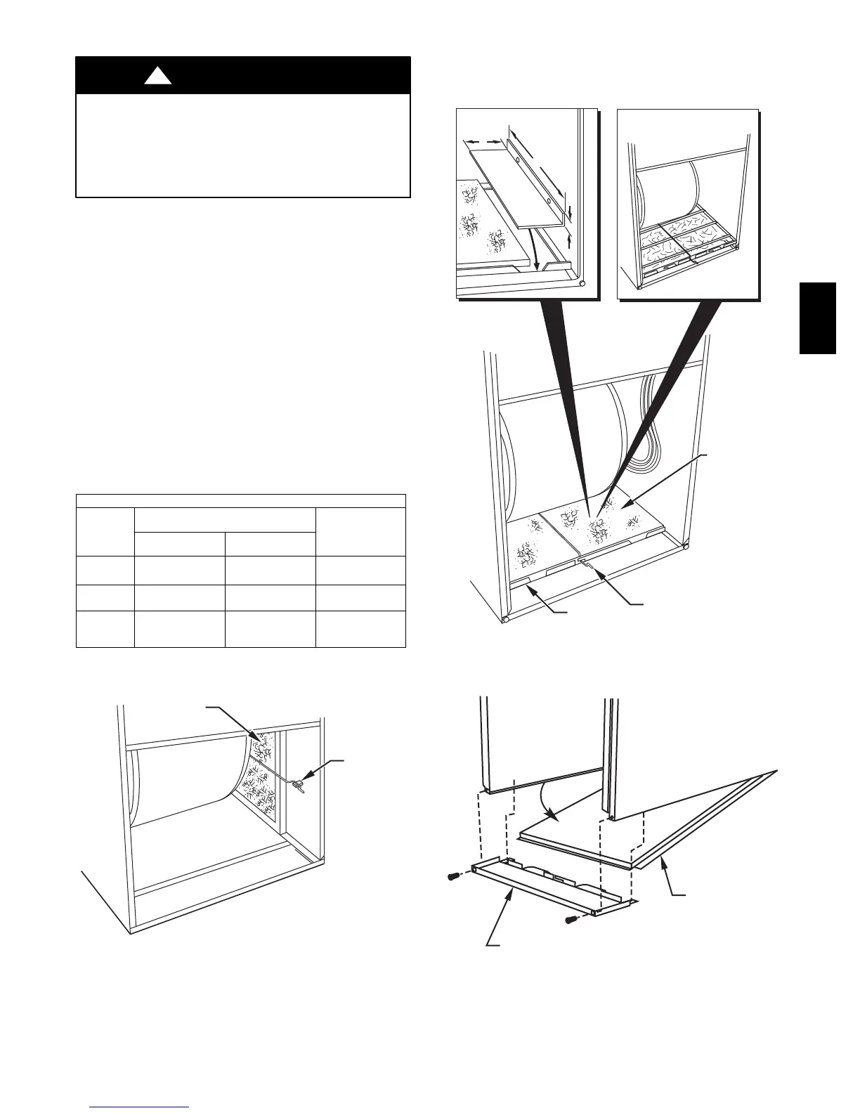
The air filter arrangement will vary due to application, furnace
orientation, and filter type. The filter may be installed in an
external Filter/Media cabinet (if provided) or the furnace blower
compartment.
If a factory-supplied external Filter/Media cabinet is provided,
instructions for its application, assembly, and installation are
packaged with the cabinet. The Filter/Media cabinet can be used
with a factory--specified washable filter or a factory-specified
high-efficiency disposable filter (see cabinet instructions).
If installing the filter in the furnace blower compartment,
determine location for filter and relocate filter retaining wire if
necessary. See Table 4 to determine correct filter size for desired
filter location. Table 4 indicates filter size and location for this
furnace. See Fig. 2 for location and size of bottom and side
return-air openings.
Table 4 – Filter Information
AIR FILTER LOCATED IN BLOWER COMPARTMENT
Furnace
Casing
Width
In. (mm)
F i l t e r S i z e --- I n . ( m m )
Filter Type
Framed
Side Return*{ Bottom Return*
17--- 1/2
(445)
(1) 16 X 25 X 3/4
(406 X 635 X 19)
(1) 16 X 25 X 3/4
(406 X 635 X 19)
Washable
21
(533)
(1) 16 X 25 X 3/4
(406 X 635 X 19)
(1) 20 X 25 X 3/4
(508 X 635 X 19)
Washable
24---1/2
(622)
(1 or 2) 16 X 25
X3/4
(406 X 635 X 19)
(1) 24 X 25 X 3/4
(609 X 635 X 19)
Washable
*Alternate sizes can be ordered from your distributor or dealer.
{ Upflow only. Alternate sizes and additional filters may be ordered from
your dealer.
FILTER
RETAINER
FILTER
A08587
Fig. 26 -- Filter Installed for Side Inlet
FILTER
FILTER
SUPPORT
FILTER
RETAINER
17
1
⁄
2
-IN. (444mm) WIDE
CASINGS ONLY:
INSTALL FIELD-SUPPLIED
FILTER FILLER STRIP
UNDER FILTER.
1″
24
1
/
2
″
3″
21-IN. (533mm) WIDE
CASINGS ONLY:
SUPPORT RODS (3)
EXTEND 1/4" (6mm) ON
EACH SIDE OF FILTER AND
REST ON CASING FLANGE
(76mm)
(533mm)
(25.4mm)
A08605
Fig. 27 -- Bottom Filter Arrangement
BOTTOM
CLOSURE
PANEL
FRONT FILLER
PANEL
A93047
Fig. 28 -- Removing Bottom Closure Panel
352AAV