WARNING: Never use matches, candles, flame, or
other sources of ignition to check for gas leakage. Use a
soap-and-water solution. Failure to follow this warning
could result in a fire, personal injury, or death.
16. Replace main furnace door.
VI. SERVICING HOT SURFACE IGNITOR
The ignitor does NOT require annual inspection. Check ignitor
resistance before removal.
1. Turn off gas and electrical supplies to furnace.
2. Remove main furnace door.
3. Disconnect ignitor wire connection.
4. Check ignitor resistance.
a. Using an ohm meter, check resistance across both ignitor
leads in connector.
b. Cold reading should be between 45 ohms and 90 ohms.
c. If ohm reading is higher than 110 ohms, ignitor is
cracked and must be replaced.
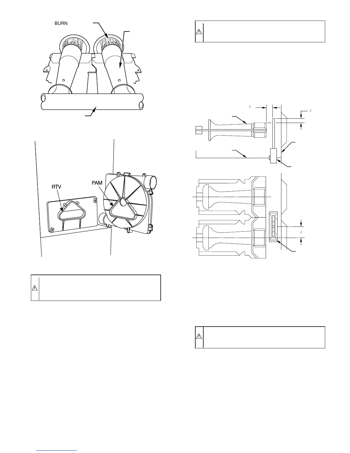
5. Remove ignitor.
a. While spreading ignitor bracket legs outward, use hand
to GENTLY guide ignitor out of burner box.
CAUTION: The ignitor is fragile. DO NOT allow it to
hit the side of the burner box opening while removing or
replacing it.
b. Inspect ignitor for a white area indicating a crack may be
present. If found, replace ignitor.
NOTE: A small crack cannot be seen on a new ignitor. After a
period of operation, a white area will be visible around the crack.
6. After inspecting or replacing ignitor, install it into burner
box by gently pushing ignitor into bracket until bracket legs
fully secure ignitor. (See Fig 11.)
7. Connect ignitor wire connection.
8. Turn on gas and electrical supplies to furnace.
9. Check furnace operation through 2 heat operating cycles.
10. Replace main furnace door.
VII. ELECTRICAL CONTROLS AND WIRING
CAUTION: There may be more than 1 electrical supply
to the unit. Check accessories and cooling unit for
additional electrical supplies.
The electrical ground and polarity for 115-v wiring must be
maintained properly. Refer to Fig. 12 for field wiring information
and to Fig. 17 for unit wiring information.
NOTE: If the polarity is not correct, the STATUS LED on the
control center will flash rapidly and prevent the furnace from
operating. The control system also requires an earth ground for
proper operation of the control center and flame sensing.
The 24-v circuit contains an automotive-type, 3-amp fuse located
on the control center. (See Fig. 13.) Any direct shorts of the 24-v
wiring during installation, service, or maintenance will cause this
fuse to blow. If fuse replacement is required, use ONLY a fuse of
identical size.
Fig. 9—Burner Flame
A89020
BURNER FLAME
BURNER
MANIFOLD
Fig. 10—Gasket on Collector Box
A93081
Fig. 11—Hot Surface Ignitor Location and Burner
Assembly
A93260
BURNER
IGNITOR
13
32
"
11
32
"
7
8
"
C
L
C
L
IGNITOR
ASSEMBLY
IGNITOR
ASSEMBLY
CELL
PANEL
BURNER
BURNER BOX
—7—

 Loading...