With power to the unit disconnected, check all electrical connec-
tions for tightness. Tighten all screws on electrical connections. If
any smoky or burned connections are found, disassemble the
connection, clean all parts, strip wire, and reassemble properly and
securely.
Reconnect electrical supply to unit and observe unit through 1
complete operating cycle. Electrical controls are difficult to check
without proper instrumentation; if there are any discrepancies in
the operating cycle, contact your dealer and request service.
VIII. TROUBLESHOOTING
For an explanation of fault codes, refer to service label located on
back of main furnace door or Fig 16.
The control center stores all fault codes for a period of 5 "good or
proper" operating cycles, regardless of 115- or 24-v power
interruption.
NOTE: Removing blower access panel will open blower access
panel door switch and terminate 115-v power to control center.
Look into blower access panel sight glass for current LED status.
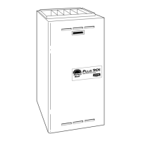
Fig. 12—Field Wiring
A93049
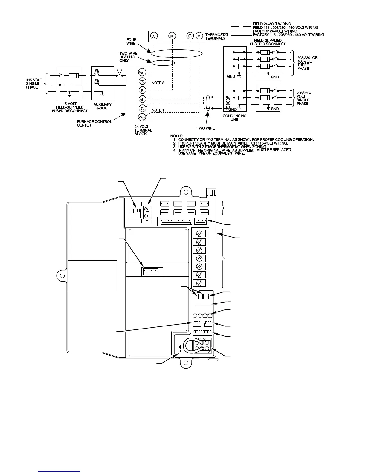
Fig. 13—Variable-Capacity Control Center
A93062
W2
COM
24V
W/W1 Y/Y2
RG
HUM
HOT SURFACE
IGNITOR CONNECTOR
EAC-ELECTRONIC AIR
CLEANER TERMINALS
(115-VAC 1 AMP MAX)
115-V
CONNECTORS
24-V THERMOSTAT
TERMINALS
PRESSURE SWITCH
CONNECTOR
HUM-HUMIDIFIER
TERMINAL
(24-VAC 0.5 AMP MAX)
TRANSFORMER
24-V CONNECTORS
3-AMP FUSE
STATUS AND DIAGNOSTIC
LED LIGHTS
AIR CONDITIONING
(A/C) SETUP SWITCH
SETUP SWITCHES
(SW) AND BLOWER
OFF DELAY SETUP
SWITCHES
MODEL PLUG
COMMUNICATION
CONNECTOR
CONTINUOUS
FAN (CF) SETUP
SWITCHES
MAIN BLOWER
CONTROL WIRE
CONNECTOR
DEHUMIDIFIER (DH)
CONNECTOR
—8—

 Loading...