IMPORTANT — READ BEFORE INSTALLING
1. Read and become familiar with these installation
instructions before installing this unit (Fig. 1).
2. Be sure the installation conforms to all applicable local
and national codes.
3. These instructions contain important information for the
proper maintenance and repair of this equipment. Re-
tain these instructions for future use.
CONTENTS
Page
SAFETY CONSIDERATIONS ........................1
INSTALLATION .................................1-13
I. Locate the Unit .............................4
II. Unit Duct Connections ......................6
III. Rig and Place Unit ..........................6
IV. Field Connections ..........................6
PRE-START-UP .................................13
START-UP ....................................13-19
I. Heating Section Start-Up and Adjustments ....13
II. Cooling Section Start-Up and Adjustments ....14
III. Indoor Airflow and Airflow Adjustments .......15
CARE AND MAINTENANCE .......................20
I. Air Filter ..................................20
SERVICE .....................................20-24
I. Cleaning .................................20
II. Lubrication ...............................20
III. Indoor Fan Performance Adjustment .........21
IV. Indoor Fan Service and Replacement .........22
V. Economizer Adjustment ....................22
VI. Power Failure .............................23
VII. Refrigerant Charge .........................23
VIII. Filter Drier ................................23
IX. Protective Devices .........................23
X. Relief Devices .............................24
XI. Control Circuit, 24 V .......................24
XII. Replacement Parts .........................24
TROUBLESHOOTING ...........................24-30
START-UP CHECKLIST ..........................CL-1
SAFETY CONSIDERATIONS
Recognize safety information. This is the safety-alert symbol
( ). When you see this symbol on the unit and in instruc-
tions or manuals, be alert to the potential for personal
injury.
Understand the signal words — DANGER, WARNING, and
CAUTION. These words are used with the safety-alert sym-
bol. Danger identifies the most serious hazards which will
result in severe personal injury or death. Warning indicates
a situation that could result in personal injury. Caution is
used to identify unsafe practices which would result in minor
personal injury or product and property damage.
WARNING:
Before performing service or mainte-
nance operations on unit, turn off main power switch
to unit. Electrical shock could cause personal injury.
1. The power supply (volts, hertz, and phase) must corre-
spond to that specified on the unit rating plate.
2. The electrical supply provided by the utility must be
sufficient to handle unit load.
3. Refer to the Locate the Unit section on page 4 and
Fig. 2 and 3 for locations of electrical inlets, condensate
drain, duct connections, and required clearances before
setting unit in place.
4. This installation must conform with local building codes
and with NEC (National Electrical Code) or NFPA
(National Fire Protection Association) 54 TIA-54-84-1.
Refer to Provincial and local plumbing or wastewater
codes and other applicable local codes.
5. Approved for outdoor installation on wood flooring or on
class A, B, or C roof covering materials.
INSTALLATION
Unit is shipped in the vertical discharge configuration (see
Fig. 4). To convert to horizontal discharge, an accessory roof
curb or accessory horizontal adapter must be used. Remove
the horizontal duct cover and attach ductwork. Seals around
duct opening must be tight. See Fig. 5. To convert to concen-
tric air distribution, a field-supplied and fabricated transi-
tion piece must be used. See Fig. 6 and 7.
All units can be connected to existing duct systems that are
properly sized and designed to handle an airflow of 300 to
500 cfm per each 12,000 Btuh of rated cooling capacity.
NOTE: When installing any accessory item, see the manu-
facturer’s installation instructions packaged with the
accessory.Aqualified installer or agency must use only factory-
authorized kits or accessories when modifying this unit.
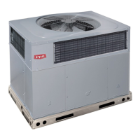
Fig.1—Typical 542J Unit
installation, start-up and
service instructions
SINGLE PACKAGE ROOFTOP
HEAT PUMP UNITS
542J
Size 150,180
13 and 15 Tons
Cancels: II 542J-150-1 II 542J-150-2
2/15/97