17
Heating
When the thermostat initiates a call for First Stage Heating by
closing its W1 contacts, a 24-v signal is conveyed to the CTB’s
TSTAT terminal strip at W1. An internal path passes this signal to
connector DDC/TSTAT pin 5. A harness wire carries this signal to
Fan Speed Relay board pin J1-2. Relay K1 is energized. The relay
board’s output to VFD at pin J2-3 is energized, providing a
24VDC signal to VFD terminal 15. The VFD starts the indoor fan
motor, runs at 60 Hz for full/high speed operation.
When space temperature rises to satisfy the thermostat W1 de-
mand, contact W1 opens de-energizing terminal W1. Relay K1 is
de-energized. The relay board output at J2-3 to the VFD is re-
moved.
524J, 548J/549J/551J/558J SERIES
Indoor fan motor ramps down to stop.
580J/581J SERIES
The IGC’s fan-off delay sequence will energize relay K3 for
45-seconds, causing the VFD to operate the indoor fan motor
at 40 Hz (low speed) for 45-seconds, then indoor fan motor
will ramp down to stop.
Operating Fan for Test and Balance
During the Test and Balance procedure, it is necessary to operate
the supply fan in High Speed without concurrent operation of the
Cooling or Heating systems. Use the following procedure to force
the fan speed to High.
UNITS WITHOUT ACCESSORY KEYPAD
1. Set the space thermostat to SYSTEM OFF and FAN in
AUTO.
2. Disconnect unit power. Lock-out/tag out.
3. Open the fan access panel and locate the VFD (see
Fig. 6-23 for your specific unit).
4. Locate and connect the WHT and YEL wires extending
from the VFD. The two wires are bundled together using
the label shown in Fig. 24.
Fig. 24 — High Speed Test Label
5. Locate pressure ports or pitot tubes in the return duct and
supply duct to measure external static pressure. See
Fig. 25 for typical locations.
6. Restore unit power.
7. Set the space thermostat to FAN CONT.
8. Check the motor speed with stroboscope or similar tool.
Motor shaft speed must be in 1725 to 1760 rpm (28.8 to
29.3 r/s) range for High Speed.
9. Replace the fan access panel.
10. Perform test and balance procedure.
11. Adjust the supply fan speed according to base unit instruc-
tions to deliver the project selection cfm value. Ensure the
selection cfm value is not lower that the “Min cfm Per Fan
Motor Type” for this unit-size as found in Tables 2-9 on
page 4.
To restore the unit to ready-to-start condition, disconnect the
unit power and lock-out/tag-out, set the space thermostat to
FAN AUTO, remove the test pressure ports from the external duct
locations, and disconnect the WHT and YEL wires. Replace the
supply fan access panel. Restore unit power.
UNIT WITH ACCESSORY VFD KEYPAD
1. Set the space thermostat to SYSTEM OFF and FAN in
AUTO.
2. Disconnect unit power. Lock-out/tag-out.
3. Open the fan access panel (see Fig. 6-23 for specific unit).
4. Locate pressure ports or pitot tubes in the return duct and
supply duct to measure external static pressure. See
Fig. 25 for typical locations.
5. Restore unit power.
6. Set the space thermostat to FAN CONT.
7. At the VFD keypad, tap the HAND key and then tap the
UP arrow button to increase the motor speed until 60.0 is
displayed on the display screen.
8. Check the motor speed with stroboscope or similar tool.
Motor shaft speed must be in 1725 to 1760 rpm (28.8 to
29.3 r/s) range for High Speed.
9. Replace the fan access panel.
10. Perform Test and Balance procedure.
11. Adjust the supply fan speed according to base unit instruc-
tions to deliver the project selection cfm value. Ensure the
selection cfm value is not lower that the “Min cfm Per Fan
Motor Type” for this unit-size as found in Tables 2-9 on
page 4.
To restore the unit to ready-to-start condition, tap the DOWN ar-
row button to reduce motor speed until the 40.0 is displayed on the
display screen and then tap the AUTO key. Disconnect the unit
power and lock-out/tag-out, set the space thermostat to FAN
AUTO. Remove the test pressure ports from the external duct
locations. Restore unit power.
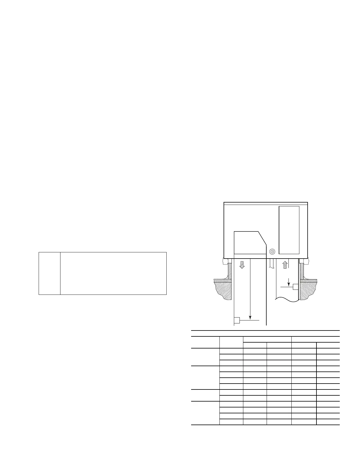
Fig. 25 — Measuring External Static Pressure — Distance
Below Unit Base
***
IMPORTANT
***
CONNECT WHITE & YELLOW WIRES
FOR HIGH SPEED BLOWER TEST
DISCONNECT FOR NORMAL OPERATION
48TM504557
SUPPLY
AIR
RETURN
AIR
A
B
AHRI PRESSURE LOCATIONS
MODEL SIZES
SUPPLY AIR [A] RETURN AIR [B]
in. mm in. mm
581J/551J
07-12 43.5 1100 12 310
14 64.5 1640 14 350
17-28 83 2110 19 490
580J/558J
07 32 830 10 260
08-14 43.5 1100 12 310
16 64.5 1640 14 350
17-30 83 2110 19 490
549J
07-09 43.5 1100 12 310
12 44.5 1130 13 330
548J
07 32 830 10 260
08-12 43.5 1100 12 310
14 44.5 1130 14 350
17-24 83 2110 19 490