18
SERVICE
Figures 6-23 show the location of the VFD option in the various
units covered by this document.
2-Speed Indoor Fan Motor Option Components
The 2-Speed Indoor Fan Motor factory option is comprised of
three major components and related connecting harnesses:
1. Fan Speed Relay Board
2. Variable Frequency Drive
3. Indoor Fan Motor, designed for use with VFD
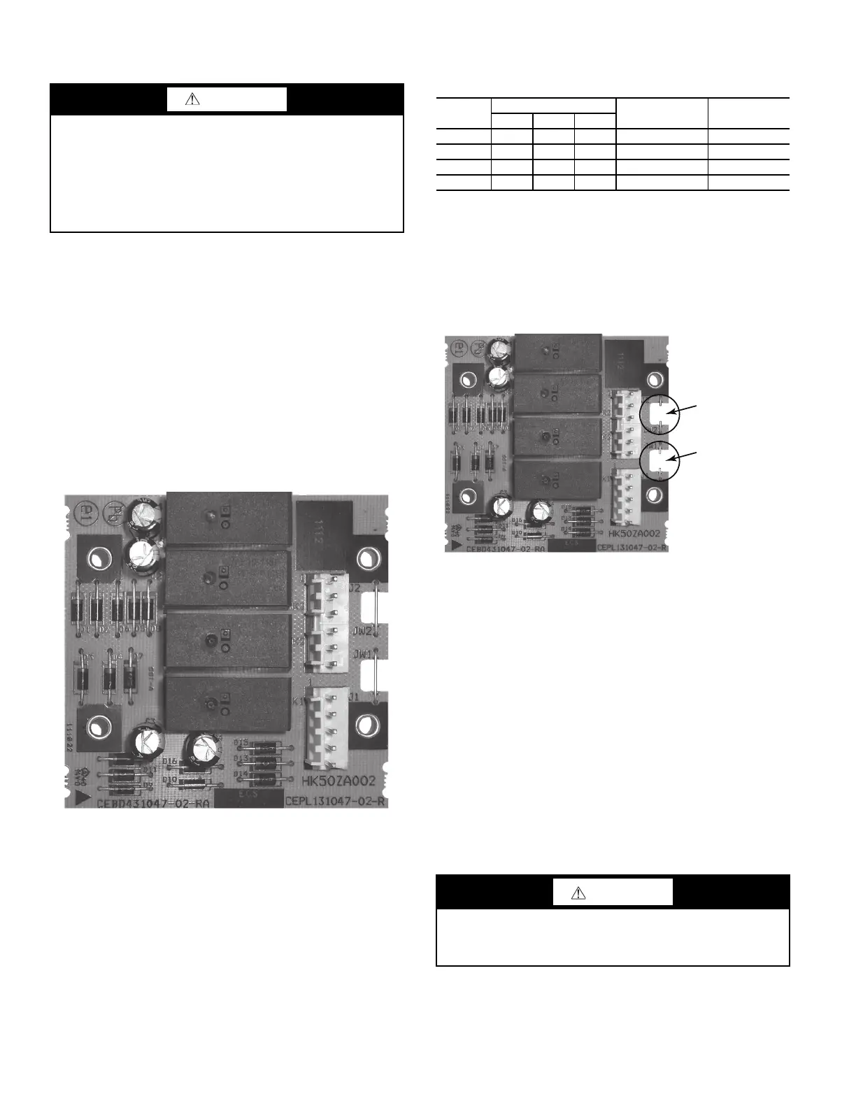
Fan Speed Relay Board
This board (Part Number: HK50ZA002) is designated as the VFD
Fan Board on the unit wiring diagram labels. It is a small (3.0 x
3.12 in., 76 x 79 mm) printed circuit board with four SPDT con-
trol relays. See Fig. 26. There is no software on this board. The
relay board is located in the unit’s main control box; refer to unit
label diagram for Component Location view.
Fig. 26 — VFD Fan Board
The board is arranged in two separate circuits with individual
pin connectors. Connector J1 is connected to the 24-vac input
signal circuit with the four relay coils. Connector J2 is connect-
ed to the 24-VDC output circuit that connects to the VFD’s ter-
minal strip. See Fig. 28 (on page 19) for a simplified connec-
tion schematic for Fan Speed Relay board and the VFD.
In this 2-Speed Indoor Fan Motor application, there are three
inputs to the relay board, originating from the space thermo-
stat’s G, Y2 and W1 terminals. An input from terminal G (for
continuous fan operation for ventilation or from a Y1 call) will
result in the VFD starting the indoor fan motor and running the
motor at LOW speed. An input from either Y2 or W1 will re-
sult in the VFD running the indoor fan motor at HIGH speed.
See Table 10 for relay operation for each unit mode. Relay K4
is not used in this 2-speed application.
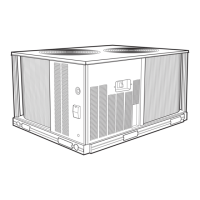
Configuration Jumpers
The relay board has two configuration jumpers, marked JW1
and JW2. For this 2-speed motor application, both jumpers
must be cut and open (see Fig. 27). Factory-installed boards
will have these jumpers cut. Service replacement boards have
these jumpers intact; servicer must cut both jumpers when in-
stalling a new service board. Failure to cut these jumpers will
cause continuous fan motor operation.
Fig. 27 — Jumpers JW1 and JW2 Cut for
Two-Speed Fan Board Configuration
Variable Frequency Drive
The VFD switches the indoor fan motor speed between
full/high speed (60 Hz motor operation) and reduced/low
speed (40 Hz motor operation) as required by
ASHRAE 90.1-2016 and IECC-2015 requirements for two-
stage HVAC units. The VFD is factory-configured to match
the current and power requirements for each motor selection
and all wiring connections are completed by the factory; no
field adjustments or connections are necessary.
While the basic VFD retains all of its standard capabilities, the
VFD 2-speed application uses only a limited portion of these
features to provide two discrete output speeds to the motor.
Consequently the VFD is not equipped with a keypad. A
keypad is available as an accessory (Part
Number: CRDISKIT001A00) ACH550/ACS320 or (Part
Number: CRDISKIT003A00) ACH580 for field-installation or
expanded service access to VFD parameter and troubleshoot-
ing tables.
CAUTION
EQUIPMENT DAMAGE HAZARD
Failure to follow this caution will result in equipment
damage.
DO NOT exceed the recommended minimum Hz or cfm
settings. Operating these units at a Hz setting below 40 Hz or
at a cfm below the minimums listed in Tables 2-9 (page 4)
will result in damage to the unit.
Table 10 — Two-Speed Configuration Logic
(Thermostat Control)
INPUT
RELAY COIL STATUS
CONTROLLING
OUTPUT
FAN MOTOR
SPEED
K1 K2 K3
G Off Off On K3 Low (40 Hz)
Y1 Off Off On K3 Low (40 Hz)
Y2 Off On On K2 High (60 Hz)
W1 On On On K1 High (60 Hz)
CAUTION
CONFIGURATION OVERRIDE HAZARD
Do not use start-up assistant on this VFD application. Use of
start-up assistant will override the factory VFD configurations.
Cut Jumper JW2
- as shown
Cut Jumper JW1
- as shown