—16—
C. Compressor Overload
This overload interrupts power to the compressor when
either the current or internal motor winding temperature
becomes excessive, and automatically resets when the inter-
nal temperature drops to a safe level. This overload may
require up to 60 minutes (or longer) to reset. If the internal
overload is suspected of being open, disconnect the electrical
power to the unit and check the circuit through the overload
with an ohmmeter or continuity tester.
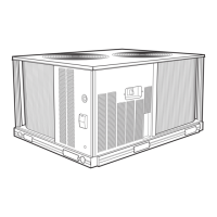
D. Advanced Scroll Temperature Protection (ASTP)
Advanced Scroll Temperature Protection (ASTP) is a form of
internal discharge temperature protection that unloads the
scroll compressor when the internal temperature reaches
approximately 300 F. At this temperature, an internal bi-
metal disk valve opens and causes the scroll elements to sep-
arate, which stops compression. Suction and discharge pres-
sures balance while the motor continues to run. The longer
the compressor runs unloaded, the longer it must cool before
the bi-metal disk resets. See Fig. 12.
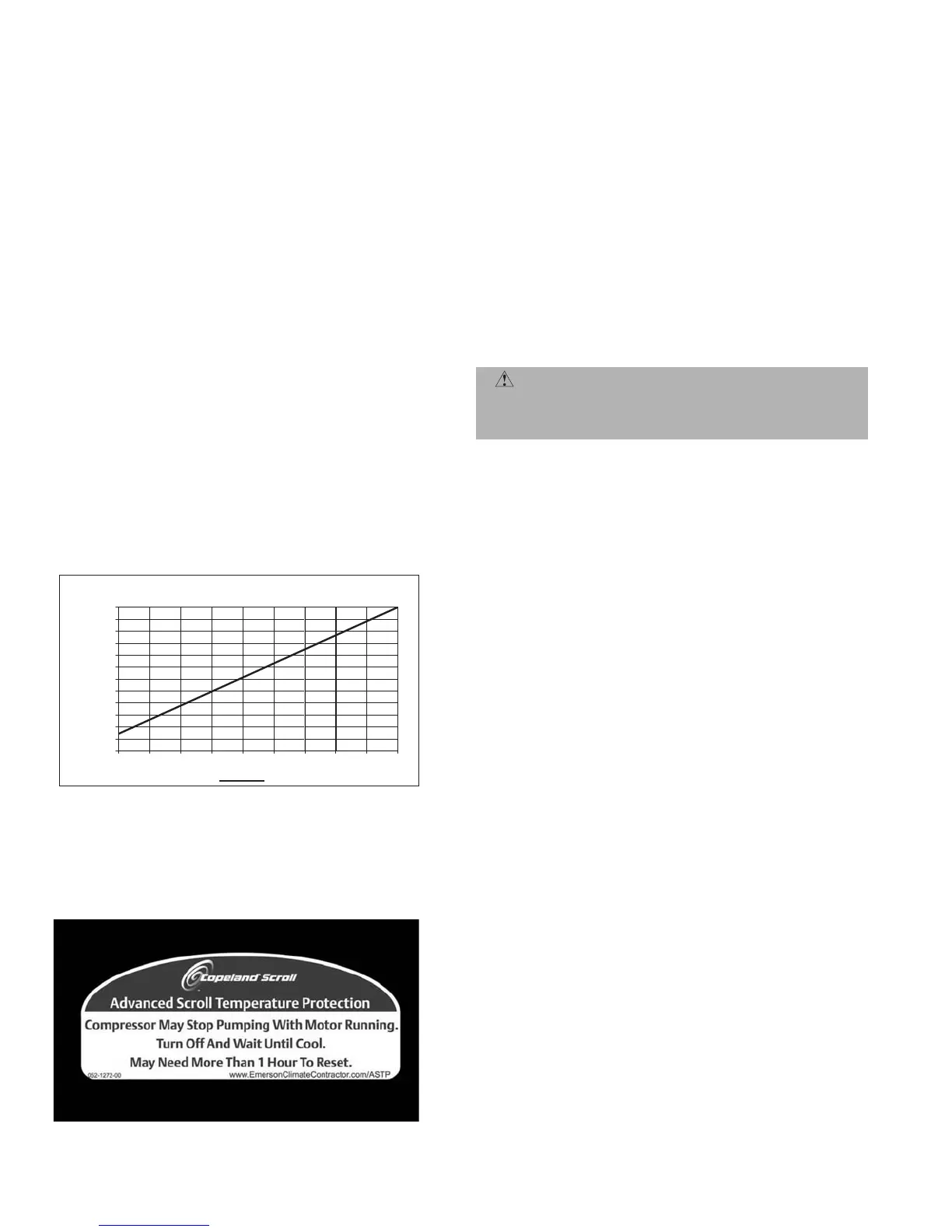
To manually reset ASTP, the compressor should be stopped
and allowed to cool. If the compressor is not stopped, the
motor will run until the motor protector trips, which occurs
up to 90 minutes later. Advanced Scroll Temperature Protec-
tion will reset automatically before the motor protector
resets, which may take up to 2 hours. A label located above
the terminal box identifies Copeland Scroll compressor
models (ZR94, 108 and 125) that contain this technology. See
Fig. 13.
E. Compressor Lockout Device
The compressor lockout (CLO) device prevents the compres-
sor from starting or running in a high pressure, loss-of-
charge or freeze-stat open situation. Reset the CLO device by
setting the thermostat to eliminate cooling demand and
return it to the original set point. If the system shuts down
again for the same fault, determine the possible cause before
attempting to reset the CLO device.
F. S ta r t Un it
The field disconnect is closed, the fan circuit breaker is
closed, and the space thermostat is set above ambient so that
there is no demand for cooling. Only the crankcase heater
will be energized.
Next, reset space thermostat below ambient so that a call for
cooling is ensured.
NOTE: Do not use circuit breaker to start and stop the com-
pressor except in an emergency.
G. Adjust Refrigerant Charge
Unit must be charged in Cooling mode only. Refer to Cooling
Charging Charts, Fig. 14-18 and to Table 7 for maximum
charge level. Do not exceed maximum refrigerant charge. For
applications with line lengths greater than 100 ft, contact
Bryant representative. Vary refrigerant until the conditions
of the chart are met. Note that charging charts are different
from type normally used. Charts are based on charging the
units to the correct subcooling for the various operating con-
ditions. Accurate pressure gage and temperature sensing
device are required. Connect the pressure gage to the service
port on the liquid line service valve. Mount the temperature
sensing device on the liquid line, close to the liquid line ser-
vice valve and insulate it so that outdoor ambient tempera-
ture does not affect the reading. Indoor airflow must be
within the normal operating range of the unit. Operate unit
a minimum of 15 minutes. Ensure pressure and temperature
readings have stabilized. Plot liquid pressure and tempera-
ture on chart and add or reduce charge to meet curve. Adjust
charge to conform with charging chart, using the liquid pres-
sure and temperature to read chart.
If the liquid line sight glass is cloudy, check refrigerant charge
again. Ensure all fans are operating. Also ensure maximum
allowable liquid lift has not been exceeded. If charged per
chart and if the sight glass is still cloudy, check for a plugged
filter drier or a partially closed solenoid valve. Replace or
repair, as needed.
CAUTION: Never charge liquid into the low-pressure
side of system. Do not overcharge. During charging or
removal of refrigerant, be sure indoor-fan system is
operating.
0
10
20
30
40
50
60
70
80
90
100
110
120
0 102030405060708090
Compressor Unloaded Run Time (Minutes)
Recommended Cooling Time
(Mi
nut
es)
*Times are approximate.
NOTE: Various factors, including high humidity, high ambient tempera-
ture, and the presence of a sound blanket will increase cool-down
times.
Fig. 12 — Recommended Minimum Cool-Down Time After
Compressor is Stopped*
Fig. 13 — Advanced Scroll Temperature Protection Label
 Loading...


