8. Check for gas leaks at the field-installed and factory-
installed gas lines after all piping connections have been
completed. Use soap-and-water solution (or method speci-
fied by local codes and/or regulations).
IX. INSTALL DUCT CONNECTIONS
The unit has duct flanges on the supply- and return-air openings on
the side and bottom of the unit. For downshot applications, the
ductwork connects to the roof curb (See Fig. 2 and 3 for
connections sizes and locations).
A. CONFIGURING UNITS FOR DOWNFLOW (VERTI-
CAL) DISCHARGE
WARNING: Before performing service or maintenance
operations on the system, turn off main power to unit.
Electrical shock could cause serious injury or death.
1. Open all electrical disconnects before starting any service
work.
2. Remove return duct cover located on duct panel by breaking
connecting tabs with screwdriver and a hammer (See Fig.
10A & 10B).
3. To remove supply duct cover, break front and right side
connecting tabs with a screwdriver and a hammer. Push
louver down to break rear and left side tabs (See Fig. 10A
& 10B).
4. If unit ductwork is to be attached to vertical opening flanges
on the unit composite base (jackstand applications only), do
so at this time.
CAUTION: Collect ALL screws that were removed. Do
not leave screws on rooftop as permanent damage to the
roof may occur.
5. It is recommended that the unit base insulation around the
perimeter of the vertical return-air opening be secured to the
unit base with aluminum tape. Applicable local codes may
require aluminum tape to prevent exposed fiberglass.
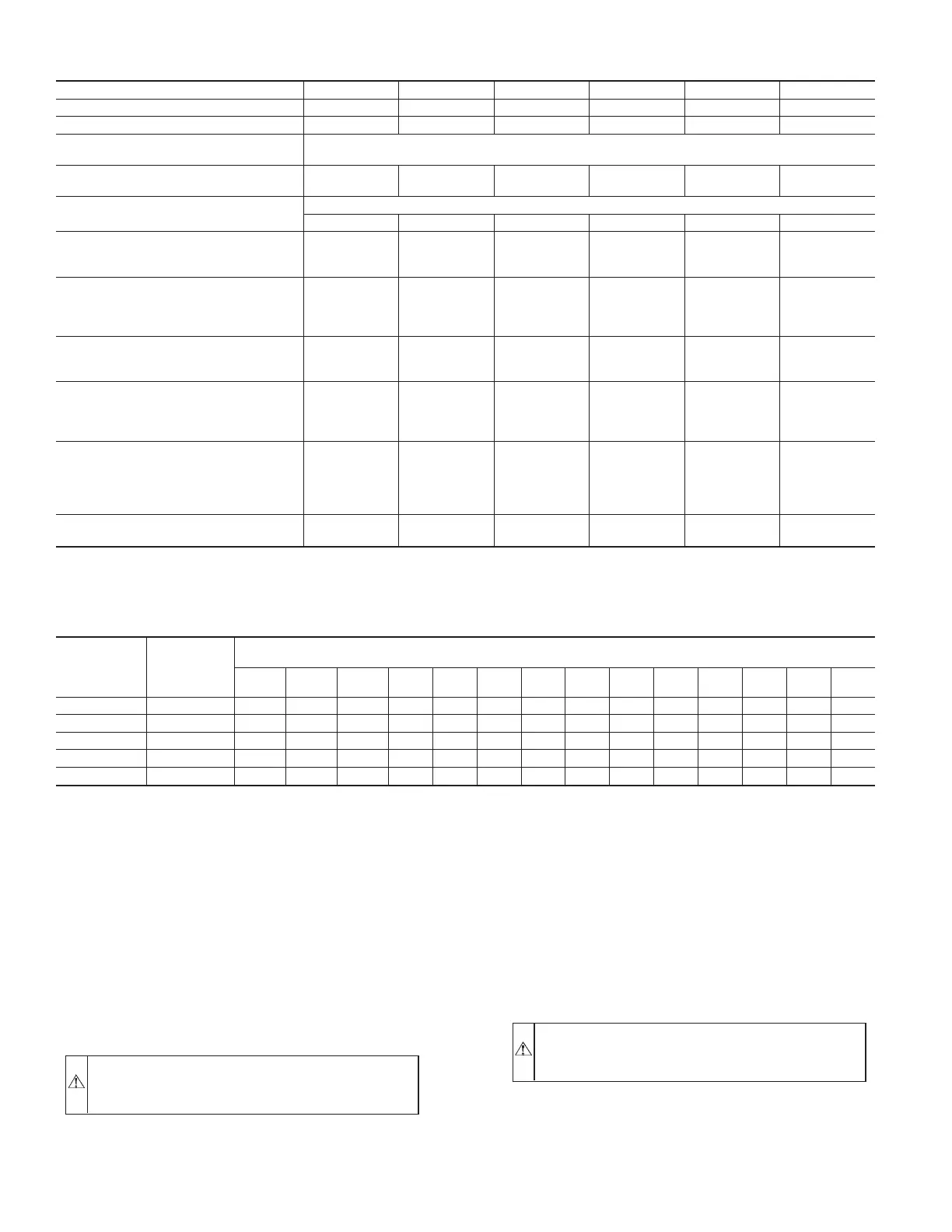
TABLE 2—PHYSICAL DATA—UNIT 583A (CONTINUED)
UNIT SIZE 583A 048090 048115 048130 060090 060115 060130
NOMINAL CAPACITY (ton) 444555
OPERATING WEIGHT (lb.) 421 421 421 468 468 468
COMPRESSORS
Quantity
Scroll
1
REFRIGERANT (R-22)
Quantity (lb.)
8.3 8.3 8.3 8.1 8.1 8.1
REFRIGERANT METERING DEVICE
Orifice ID (in.)
Acutrol Device
.034 .034 .034 .032 .032 .032
CONDENSER COIL
Rows...Fins/in.
Face Area (sq ft)
2...17
12.3
2...17
12.3
2...17
12.3
2...17
16.4
2...17
16.4
2...17
16.4
CONDENSER FAN
Nominal Cfm
Diameter (in.)
Motor Hp (Rpm)
3300
22
¼ (1100)
3300
22
¼ (1100)
3300
22
¼ (1100)
3300
22
¼ (1100)
3300
22
¼ (1100)
3300
22
¼ (1100)
EVAPORATOR COIL
Rows...Fins/in.
Face Area (sq ft)
4...15
4.7
4...15
4.7
4...15
4.7
4...15
4.7
4...15
4.7
4...15
4.7
EVAPORATOR BLOWER
Nominal Airflow (Cfm)
Size (in.)
Motor Hp (Rpm)
1600
11X10
3/4 (1075)
1600
11X10
3/4 (1075)
1600
11X10
3/4 (1075)
1750
11X10
1.0 (1075)
1750
11X10
1.0 (1075)
1750
11X10
1.0 (1075)
FURNACE SECTION*
Burner Orifice No. (Qty...Drill Size)
Natural Gas
Burner Orifice No. (Qty...Drill Size)
Propane Gas
3...38
3...46
3...33
3...42
3...31
3...41
3...38
3...46
3...33
3...42
3...31
3...41
RETURN-AIR FILTERS (in.)†
Throwaway
24X30 24X30 24X30 24X30 24X30 24X30
* Based on altitude of 0 to 2000 ft.
† Required filter sizes shown are based on the larger of the ARI (Air Conditioning and Refrigeration Institute) rated cooling airflow or the heating airflow velocity of 300
ft/minute for high-capacity type. Air filter pressure drop for non-standard filters must not exceed 0.08 in. wg.
TABLE 3—MAXIMUM GAS FLOW CAPACITY*
NOMINAL
IRON PIPE,
SIZE
(IN.)
INTERNAL
DIAMETER
(IN.)
LENGTH OF PIPE, FT†
10 20 30 40 50 60 70 80 90 100 125 150 175 200
½ .622 175 120 97 82 73 66 61 57 53 50 44 40 — —
¾ .824 360 250 200 170 151 138 125 118 110 103 93 84 77 72
1 1.049 680 465 375 320 285 260 240 220 205 195 175 160 145 135
1¼ 1.380 1400 950 770 600 580 530 490 460 430 400 360 325 300 280
1½ 1.610 2100 1460 1180 990 900 810 750 690 650 620 550 500 460 430
* Capacity of pipe in cu ft of gas per hr for gas pressure of 0.5 psig or less. Pressure drop of 0.5-in. wg (based on a 0.60 specific gravity gas). Refer to Table C-4, National
Fire Protection Association NFPA 54.
† This length includes an ordinary number of fittings.
—10—