e. Loosen setscrew(s) that secures wheel to motor shaft.
Remove screws that secure motor mount brackets to
housing, and slide motor and motor mount out of
housing.
2. Remove and clean blower wheel as follows:
a. Ensure proper reassembly by marking wheel orientation.
b. Lift wheel from housing. When handling and/or cleaning
blower wheel, be sure not to disturb balance weights
(clips) on blower wheel vanes.
c. Remove caked-on dirt from wheel and housing with a
brush. Remove lint and/or dirt accumulations from wheel
and housing with vacuum cleaner, using soft brush
attachment. Remove grease and oil with mild solvent.
d. Reassemble wheel into housing.
e. Reassemble motor into housing. Be sure setscrews are
tightened on motor shaft flats and not on round part of
shaft.
f. Reinstall unit access panel.
3. Restore electrical power to unit. Start unit and check for
proper blower rotation and motor speeds during heating and
cooling cycles.
C. FLUE GAS PASSAGEWAYS
To inspect the flue collector box and upper areas of the heat
exchanger:
1. Remove the combustion blower wheel and motor assembly
according to directions in the Combustion-Air Blower
section.
2. Remove the 3 screws holding the blower housing to the flue
collector box cover (See Fig. 31–34).
3. Remove the 12 screws holding the flue collector box cover
(See Fig. 33–34) to the heat exchanger assembly. Inspect
the heat exchangers.
4. Clean all surfaces, as required, using a wire brush.
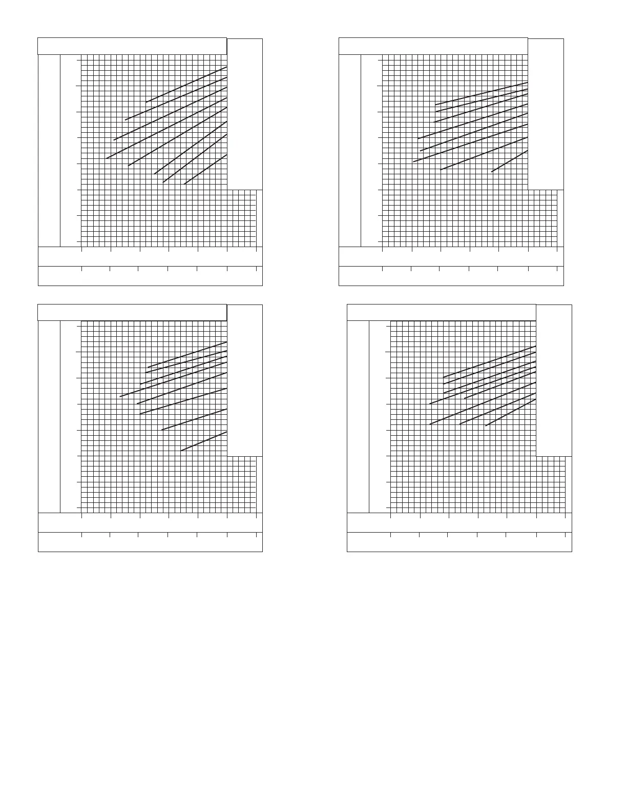
SUCTION LINE PRESSURE (KILOPASCALS)
SUCTION LINE PRESSURE (PSIG)
-14 1016212732
SUCTION LINE TEMPERATURE (°F)
SUCTION LINE TEMPERATURE (°C)
689
620
551
483
414
345
276
207
100
90
80
70
60
50
40
30
30 40 50 60 70 80 90
OUTDOOR TEMP
° F ° C
115 46
45 7
55 13
65 18
75 24
95 35
105 41
85 29
(030) 60HZ CHARGING CHART
C99046
Fig. 26—Cooling Charging Chart, 583A030 Units
Fig. 28—Cooling Charging Chart, 583A042 Units
C00052
SUCTION LINE PRESSURE (KILOPASCALS)
SUCTION LINE PRESSURE (PSIG)
-14 1016212732
SUCTION LINE TEMPERATURE (°F)
SUCTION LINE TEMPERATURE (°C)
689
620
551
483
414
345
276
207
100
90
80
70
60
50
40
30
30 40 50 60 70 80 90
OUTDOOR TEMP
° F ° C
115 46
45 7
55 13
65 18
75 24
95 35
105 41
85 29
(042) 60HZ CHARGING CHART
SUCTION LINE PRESSURE (KILOPASCALS)
SUCTION LINE PRESSURE (PSIG)
-14 1016212732
SUCTION LINE TEMPERATURE (°F)
SUCTION LINE TEMPERATURE (°C)
689
620
551
483
414
345
276
207
100
90
80
70
60
50
40
30
30 40 50 60 70 80 90
OUTDOOR TEMP
° F ° C
115 46
45 7
55 13
65 18
75 24
95 35
105 41
85 29
(036) 60HZ CHARGING CHART
C00051
Fig. 27—Cooling Charging Chart, 583A036 Units
SUCTION LINE PRESSURE (KILOPASCALS)
SUCTION LINE PRESSURE (PSIG)
-14 1016212732
SUCTION LINE TEMPERATURE (°F)
SUCTION LINE TEMPERATURE (°C)
689
620
551
483
414
345
276
207
100
90
80
70
60
50
40
30
30 40 50 60 70 80 90
OUTDOOR TEMP
° F ° C
115 46
45 7
55 13
65 18
75 24
95 35
105 41
85 29
(048) 60HZ CHARGING CHART
C00053
Fig. 29—Cooling Charging Chart, 583A048 Units
—26—