3. Make the following inspections:
a. Inspect for shipping and handling damages such as
broken lines, loose parts, disconnected wires, etc.
b. Inspect for oil at all refrigerant tubing connections and
on unit base. Detecting oil generally indicates a refrig-
erant leak.
c. Leak test all refrigerant tubing connections using elec-
tronic leak detector, halide torch, or liquid-soap solution.
If a refrigerant leak is detected, see the Check for
Refrigerant Leaks section.
d. Inspect all field- and factory-wiring connections. Be sure
that connections are completed and tight.
e. Ensure wires do not contact refrigerant tubing or sharp
sheet metal edges.
f. Inspect coil fins. If damaged during shipping and han-
dling, carefully straighten fins with a fin comb.
4. Verify the following conditions:
CAUTION: Do not purge gas supply into the combus-
tion chamber. Do not use a match or other open flame to
check for gas leaks. Failure to follow this warning could
result in an explosion causing serious injury or death.
a. Make sure gas line is free of air. Before lighting the unit
for the first time, perform the following with the gas
valve in the ‘‘OFF’’ position:
If the gas supply pipe was not purged before
connecting the unit, it will be full of air. It is
recommended that the ground joint union be
loosened, and the supply line be allowed to
purge until the odor of gas is detected. Never
purge gas lines into a combustion chamber.
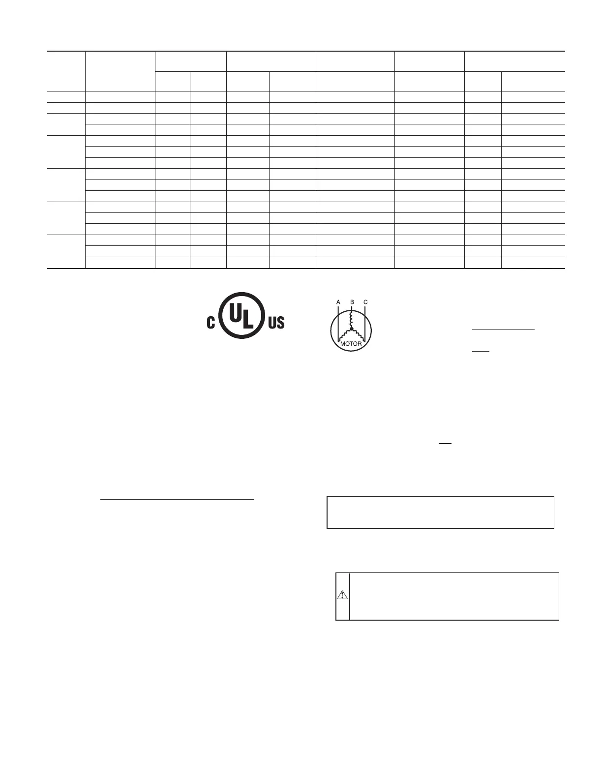
TABLE 4—ELECTRICAL DATA—UNIT 582A
UNIT
SIZE
582A
V-PH-HZ
VOLTAGE
RANGE
COMPRESSOR
OUTDOOR FAN
MOTOR
INDOOR FAN
MOTOR
POWER SUPPLY
Min Max RLA LRA FLA FLA MCA
Max Fuse or
Ckt Bkr
018 208/230–1–60 187 253 9.0 45.0 0.8 1.8 13.9 20
024 208/230–1–60 187 253 12.8 61.0 0.8 2.0 18.8 30
030
208/230–1–60 187 253 14.4 73.0 0.8 2.0 20.8 30
208/230–3–60 187 253 12.6 68.0 0.8 2.0 13.2 20
036
208/230–1–60 187 253 13.0 81.0 1.6 3.6 24.0 35
208/230–3–60 187 253 9.0 78.0 1.6 3.6 16.5 25
460–3–60 414 506 4.5 40.0 0.9 1.9 8.4 15
042
208/230–1–60 187 253 18.6 105.0 1.6 3.8 27.5 45
208/230–3–60 187 253 10.7 85.0 1.6 3.8 18.8 25
460–3–60 414 506 5.3 42.0 0.9 2.0 9.5 15
048
208/230–1–60 197 253 25.3 131.0 1.6 3.8 37.0 60
208/230–3–60 187 253 13.5 108.0 1.6 3.8 22.3 35
460–3–60 414 506 6.7 47.5 0.9 2.0 11.3 15
060
208/230–1–60 187 253 28.9 147.0 1.6 6.2 43.9 60
208/230–3–60 187 253 18.6 125.0 1.6 6.2 31.1 45
460–3–60 414 506 8.5 66.5 0.9 3.2 14.7 20
Table 4—Legend
C99024
452=5v
457=7v
455=2v
LEGEND
FLA — Full Load Amps
LRA — Locked Rotor Amps
MCA — Minimum Circuit Amps
MOCP — Maximum Overcurrent Protection
RLA — Rated Load Amps
NOTES:
1. In compliance with NEC (National Electrical Code) requirements
for multimotor and combination load equipment (refer to NEC
Articles 430 and 440), the overcurrent protective device for the
unit shall be Power Supply fuse. Canadian units may be
fuse or circuit breaker.
2. Minimum wire size is based on 60 C copper wire. If other than
60 C wire is used, or if length exceeds wire length in table,
determine size from NEC.
3. Unbalanced 3-Phase Supply Voltage
Never operate a motor where a phase imbalance in supply volt-
age is greater than 2%.
Use the following formula to determine
the percentage of voltage imbalance.
% Voltage imbalance
max voltage deviation from average voltage
= 100 x
average voltage
EXAMPLE: Supply voltage is 460-3-60.
AB = 452 v
BC = 464 v
AC = 455 v
452 + 464 + 455
Average Voltage =
3
1371
=
3
= 457
Determine maximum deviation from average voltage.
(AB) 457
(BC) 464
(AC) 457
Maximum deviation is 7 v.
Determine percent of voltage imbalance.
7
% Voltage Imbalance = 100 x
457
= 1.53%
This amount of phase imbalance is satisfactory as it is below the
maximum allowable 2%.
IMPORTANT: If the supply voltage phase imbalance is
more than 2%, contact your local electric utility company
immediately.
®
CKT BKR
—
Circuit Breaker
—13—