12
CONDENSATE TRAP
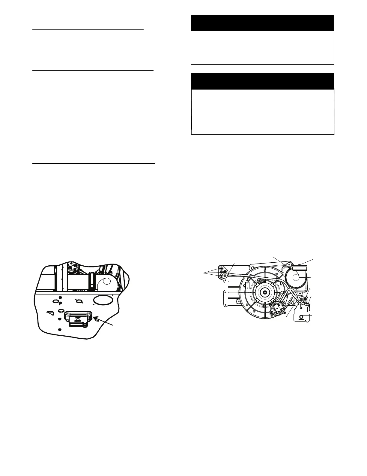
Condensate Trap -- Upflow Orientation
When the furnace is installed in the upflow position, it is not
necessary to relocate the condensate trap or associated tubing.
Refer to Fig. 9 for upflow condensate trap information. Refer to
Condensate Drain section for information how to install the
condensate drain.
Condensate Trap -- Downflow Orientation.
When the furnace is installed in the downflow position, the
condensate trap will be initially located at the upper left corner of
the collector box, as received from the factory. See the top image
in Fig. 10. When the furnace is installed in the downflow
orientation, the condensate trap must be relocated for proper
condensate drainage. See the bottom image in Fig. 10.
To Relocate the Condensate Trap:
S Orient the f urnace in the downfl ow position.
S Fig. 10 s how s the condensate t rap and tubi ng before a nd aft er
reloc ation. Refer to Fig. 10 to begin the trap convers ion.
S Refer t o Condensate Drain s ection f or informa t ion how to i nsta ll t he
condensate dra in.
Condensate Trap -- Horizontal Orientation.
Whe n t he furnace is ins t alled in the hori zontal right position, the
condensate t r ap wil l be initially located at the bottom of the collector
box, as received from the factory . See the top image in Fig. 11.
When the furnace is installed in the horizontal left position, the
condensate trap will be initially located at the top of the collector box,
as received from the factory . See the top image in Fig. 12. In both
cases t he trap must be re posit ioned on the c olle ctor box for proper
condensate dr ainage. See the bot tom i m a ges in Fig. 1 1 and 12.
A field--supplied, accessory Horizontal Installation Kit (trap
grom met) i s r equired for a ll dir e ct--vent horizont al ins tallati ons ( onl y).
The kit contains a rubbe r casing grommet des igned to se al bet w een
the f urnace casi ng and the c ondensate t r ap. See Fi g. 8.
Remove knockout.
Install grommet before
relocating condensate
trap.
NOTE: Trap grommet is required only for direct-vent
applications.
A11582
Fig. 8 -- Horizontal Drain Trap Grommet
The field--supplied, accessory horizontal drain trap grommet is
ONLY REQUIRED FOR DIRECT VENT APPLICATIONS.
It it NOT required for applications using single-- pipe or
ventilated combustion air venting.
NOTICE
The condensate trap extends below the side of the casing in
the horizontal position. A minimum of 2-- in. (51 mm) of
clearance is required between the casing side and the furnace
platform for the trap to extend out of the casing in the
horizontal position. Allow at least 1/4--in. per foot (20 mm
per meter) of slope down.
NOTICE
To Relocate the Condensate Trap:
S Remove the knockout i n t he casi ng for t he condensate trap.
S Install t he grommet in the ca sing when requir ed for dir ect--vent
horizontal appl i cations.
S Orient the furnace in the desired position.
S Allow for 2 i n. (51 mm) of c learance under neath the fur nace for the
condensate tr ap and drai n line .
S Fig. 11 shows the conde ns ate tr ap and t ubing before and a fte r
relocation i n t he hori zontal right position.
S Fig. 12 s how s the condensate t rap and tubi ng before a nd aft er
relocation i n t he hori zontal lef t posi tion.
S Refer t o the a ppropriat e fi gure t o be gin the trap convers ion.
S Refer t o Condensate Drain s ection f or informa t ion how to i nsta ll t he
condensate dra in.
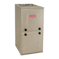
Condensate Trap
Relief Port
Collector Box
Plugs
Pressure Switch
Port
Condensate Trap
Outlet
Condensate Trap
Relief Port
Collector Box
Plug
Vent Elbow
Vent Elbow Clamp
Vent Pipe Clamp
UPFLOW TRAP CONFIGURATION
1 & 2 Stage Units
A11307
Fig. 9 -- Upflow Trap Configuration
(Appearance may vary)