33
Table 11 – Electrical Data
FURNACE SIZE
V O LT S ---
H E R T Z ---
PHASE
OPERATING VOLTAGE
RANGE*
MAXIMUM
UNIT
AMPS
UNIT
AMPACITY#
MINIMUM
WIRE
SIZE
AWG
MAXIMUM
WIRE
LENGTH
FT (M)}
MAXIMUM
FUSE OR CKT
BKR
AMPS{
Maximum* Minimum*
30026E14
1 1 5 --- 6 0 --- 1 127 104 5.1 7.3 14 50 (15.5) 15
30040E14
1 1 5 --- 6 0 --- 1 127 104 7 9.7 14 38 (11.7) 15
36040E17
1 1 5 --- 6 0 --- 1 127 104 7.5 10.3 14 36 (10.9) 15
36060E14
1 1 5 --- 6 0 --- 1 127 104 7.1 9.8 14 38 (11.5) 15
42060E17
1 1 5 --- 6 0 --- 1 127 104 9.6 12.9 14 28 (8.7) 15
48080E17
1 1 5 --- 6 0 --- 1 127 104 10 13.4 14 27 (8.4) 15
60080E21
1 1 5 --- 6 0 --- 1 127 104 12.3 16.3 12 35 (10.7) 20
60100E21
1 1 5 --- 6 0 --- 1 127 104 12.6 16.6 12 34 (10.5) 20
60120E24
1 1 5 --- 6 0 --- 1 127 104 12.4 16.4 12 35 (10.7) 20
66140E24
1 1 5 --- 6 0 --- 1 127 104 12.6 16.6 12 34 (10.5) 20
* Permissible limits of the voltage range at which the unit operates satisfactorily.
# Unit ampacity = 125 percent of largest operating component’s full load amps plus 100 percent of all other potential operating components’ (EAC, humidifier,
etc.) full load amps.
{Time---delay type is recommended.
}Length shown is as measured one way along wire path between furnace and service panel for maximum 2 percent voltage drop.
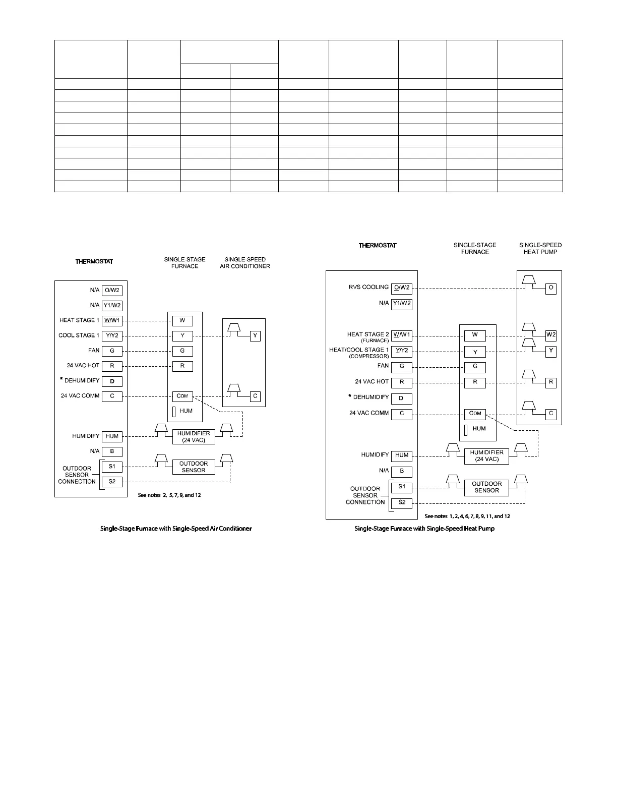
A190081
Fig. 38 -- Thermostat Wiring Diagrams
NOTES FOR THERMOSTAT WIRING DIAGRAMS
1. Heat pump MUST have a high pressure switch for HYBRID HEATr dual fuel applications.
2. Refer to outdoor equipment Installation Instructions for additional information and setup procedure.
3. If the heat pump date code is 1501E or earlier, select the “ZONE” position on the two speed heat pump control. Heat pumps with date
code 1601E and later do not have or require a “ZONE” selection.
4. Outdoor Air Temperature Sensor must be attached in all HYBRID HEATr dual fuel applications.
5. Configure the thermostat for air conditioner installations. Refer to thermostat instructions.
6. Configure thermostat for heat pump installations. Refer to thermostat instructions.
7. Configure thermostat for single-stage compressor operation. Refer to thermostat instructions.
8. Configure thermostat for HYBRID HEATr dual fuel operation. Refer to thermostat instructions.
9. NO connection should be made to the furnace HUM terminal when using a thermostat with a 24 volt humidifier output.
10. The RVS Sensing terminal “L” should not be connected. This is used internally to sense defrost operation.
11. If thermostat has internal control of heat pump balance point, DO NOT SELECT the “FURNACE INTERFACE” or “BALANCE
POINT” option on the two--speed heat pump control board. Refer to thermostat instructions.
12. Thermostat signals may vary. Consult thermostat installation instructions for more information.