20
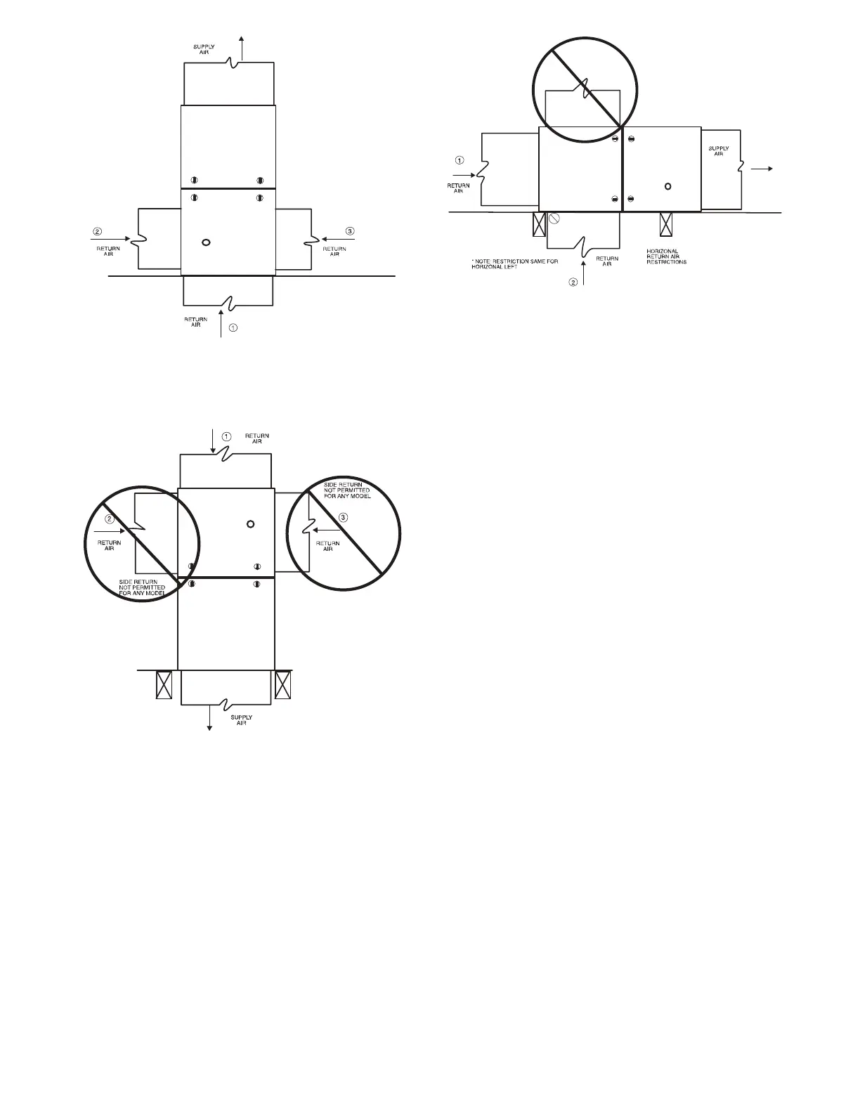
ANY COMBINATION OF 1, 2, OR 3 PERMITTED.
A11036
Fig. 22 -- Upflow Return Air Configurations and Restrictions
A11037
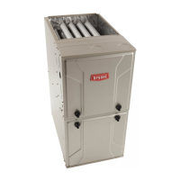
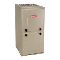
Fig. 23 -- Downflow Return Air Configurations
and Restrictions
HORIZONTAL TOP
RETURN NOT
PERMITTED FOR
ANY MODEL
A11038
Fig. 24 -- Horizontal Return Air Configurations and
Restrictions
Supply Air Connections
For a furnace not equipped with a cooling coil, the outlet duct shall
be provided with a removable access panel. This opening shall be
accessible when the furnace is installed and shall be of such a size
that the heat exchanger can be viewed for possible openings using
light assistance or a probe can be inserted for sampling the air
stream. The cover attachment shall prevent leaks.
Connect supply --air duct to flanges on furnace supply --air outlet.
Bend flange upward to 90_ with wide duct pliers. See Fig. 19. The
supply --air duct must be connected to ONLY the furnace
supply --outlet--air duct flanges or air conditioning coil casing
(when used). DO NOT cut main furnace casing side to attach
supply air duct, humidifier, or other accessories. All supply--side
accessories MUST be connected to duct external to furnace main
casing.
Return Air Connections
The return--air duct may be connected to bottom of the furnace.
The side of casing that faces downward may also be used for return
air connection. A combination of the bottom and downward
facing side may also be used. The upward facing side of the casing
cannot be used as a return air connection. See Fig. 24.