20
INSTALL CLAMPS ON DRAIN TUBE
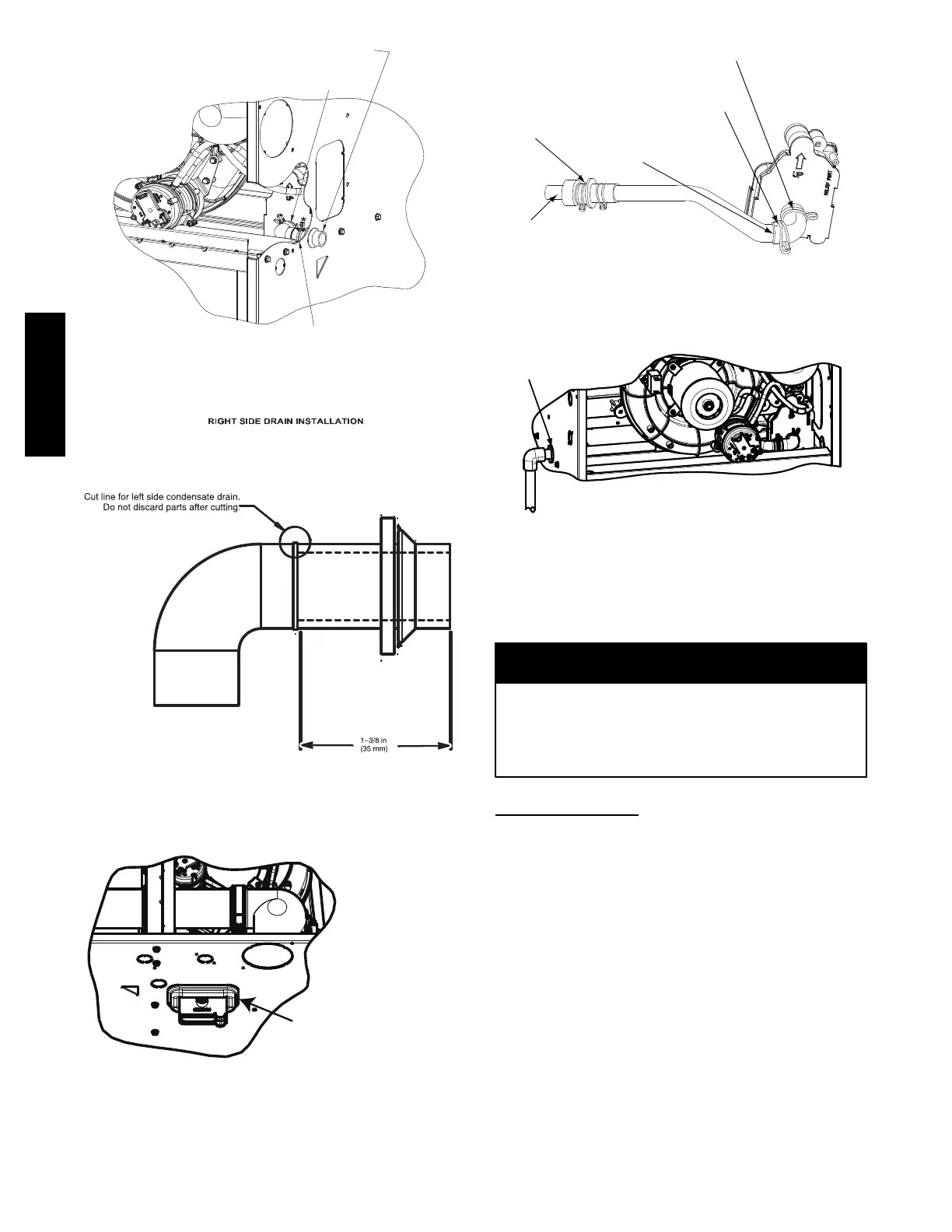
ATTACH DRAIN TUBE TO CONDENSATE
DRAIN TRAP
PULL DRAIN STUB
THROUGH CASING
OPEN SPRING CLAMP
INSERT FACTORYïSUPPLIED 1/2ïIN. CPVC
TO 3/4ïIN. PVC ADAPTER OR 1/2ïIN. CPVC PIPE
*CLAMP MAY BE LOCATED ON OUTSIDE OF DRAIN
TUBE
A11342A
Fig. 15 -- Formed Rubber Drain Grommet
A11581
Fig. 16 -- Modify Rubber Drain Elbow
Remove knockout.
Install grommet before
relocating condensate
trap.
NOTE: Trap grommet is required only for direct-vent
applications.
A11582
Fig. 17 -- Horizontal Drain Trap Grommet
s
TRAP, DRAIN ELBOW WITH DISCHARGE PIPE
Attach elbow to condensate trap
Cut formed end off
condensate drain
elbow
Connect short end
of “Z” pipe to modified
drain elbow
Factory supplied 1/2ïin. CPVC to
3/4ïin. PVC adapter
LEFT SIDE DRAIN ROUTED BEHIND INDUCER
Formed end of grommet
Open spring clamp. Insert
1/2ïin. to 3/4ïin. CPVC to
PVC adapter or 1/2ïin.
CPVC pipe
Modified drain elbow connect to
condensate trap and “Z” pipe
Formed end of
grommet
NOTE: Remove Inducer Housing for easier access, if desired.
L12F015
Fig. 18 -- Drain Trap Connection and Routing
(Appearance may vary)
INSTALLATION
This furnace is certified to leak 2% or less of nominal air
conditioning CFM delivered when pressurized to 1--in. water
column with all present air inlets, including bottom closure in
upflow and horizontal applications, air outlets, and plumbing
and electrical ports sealed.
NOTICE
Upflow Installation
NOTE: The furnace must be pitched as shown in Fig. 24 for
proper condensate drainage.
Supply Air Connections
For a furnace not equipped with a cooling coil, the outlet duct shall
be provided with a removable access panel. This opening shall be
accessible when the furnace is installed and shall be of such a size
that the heat exchanger can be viewed for possible openings using
light assistance or a probe can be inserted for sampling the air
stream. The cover attachment shall prevent leaks.
Connect supply--air duct to flanges on furnace supply--air outlet.
Bend flange upward to 90_ with wide duct pliers. See Fig. 21. The
supply--air duct must be connected to ONLY the furnace
supply--outlet--air duct flanges or air conditioning coil casing
(when used). DO NOT cut main furnace casing side to attach
supply air duct, humidifier, or other accessories. All supply--side
accessories MUST be connected to duct external to furnace main
casing.
925TA