48
2-Pipe and 1-Pipe Vent Termination
NOTE: Follow the instructions of the vent terminal manufacturer.
These instructions are provided as a reference, only.
RECOMMENDED SUPPORT FOR VENT
TERMINATIONS
It is recommended that sidewall vent terminations in excess of
24 inches (0.6 M) in vertical length be supported by EITHER
the Direct Vent Termination Kit shown in Table 12 or by
field--supplied brackets or supports fastened to the structure.
NOTICE
Determine an appropriate location for termination kit using the
guidelines provided in section “Locating The Vent Termination” in
this instruction.
1. Cut two holes, one for each pipe, of appropriate size for
pipe size being used.
2. Loosely install elbow in bracket (if used) and place as-
sembly on combustion--air pipe.
3. Install bracket as shown in Fig. 51 and 53.
NOTE: For applications using vent pipe option indicated by
dashed lines in Fig. 51 and 52, rotate vent elbow 90_ from
position.
4. Disassemble loose pipe fittings. Clean and cement using
same procedures as used for system piping. DO NOT CE-
MENT POLYPROPYLENE FITTINGS.
(Direct Vent / 2-Pipe System ONLY)
When two or more furnaces are vented near each other, two vent
terminations may be installed as shown in Fig. 51, but next vent
termination, or pair of vent terminations, must be at least 36 in.
(914 mm) away from the first two terminations. It is important that
vent terminations be made as shown in Fig. 51 to avoid
recirculation of vent gases.
Inducer Outlet Restrictor
To improve efficiency and operation of 40,000 BTUH input
models on very short vent systems, an inducer outlet restrictor is
required to be installed on the outlet of the inducer assembly. The
outlet restrictor is shipped in the loose parts bag.
To determine if the outlet restrictor is required, see Table 15.
Failure to use an outlet choke when required may result in
flame disturbance or flame sense lockout.
To install the outlet restrictor:
1. Remove the vent elbow from the inducer outlet.
2. Align the lock tabs on the outlet restrictor with the slots on
inside outlet of the inducer assembly.
3. Snap the outlet restrictor in place.
4. Re-install the vent elbow.
5. Torque vent elbow clamp 15-lb--in.
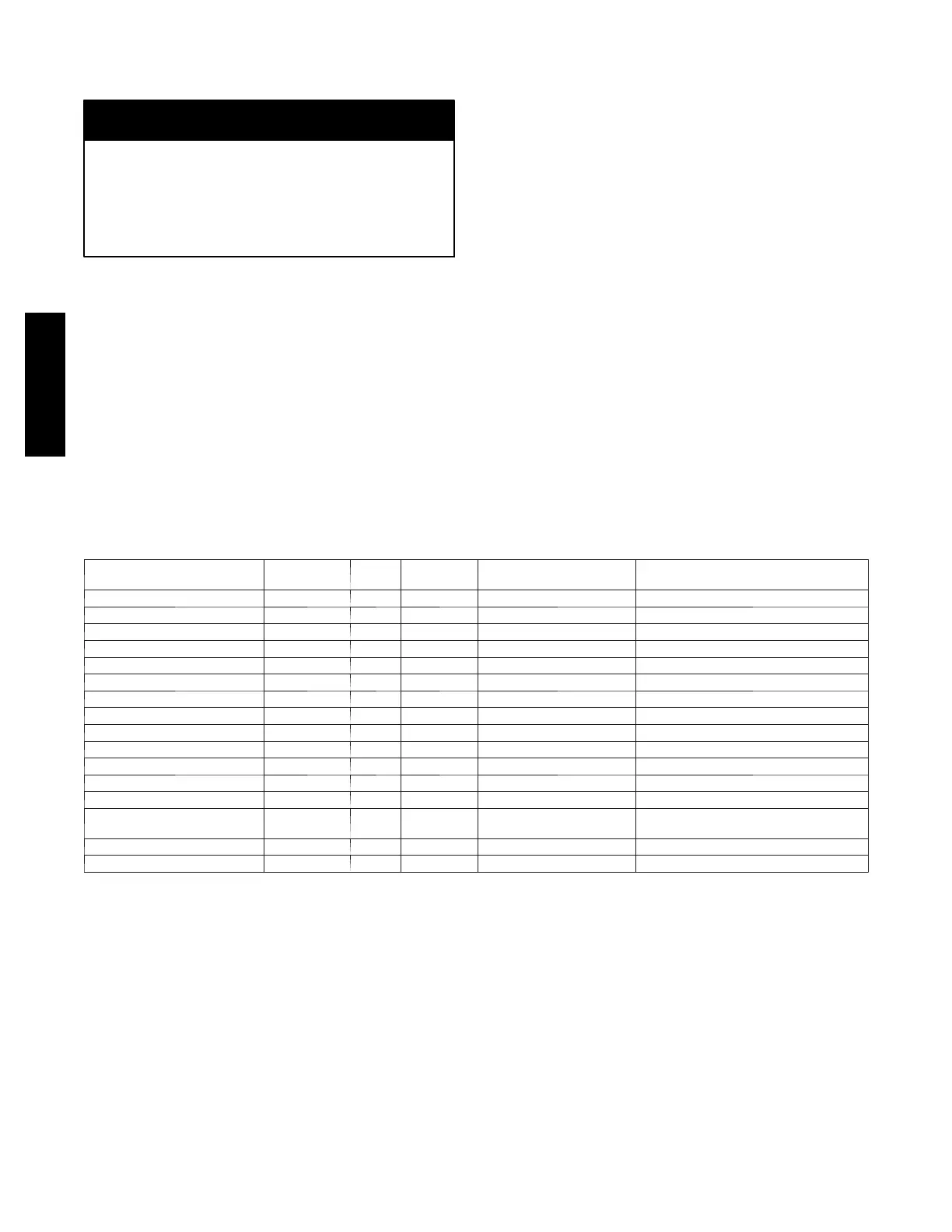
Table 13 – Approved Combustion-Air and Vent Pipe, Fitting and Cement Materials (U.S.A. Installations)
ASTM SPECIFICATION
(MARKED ON MATERIAL)
MATERIAL PIPE FITTINGS
SOLVENT CEMENT
AND PRIMERS
DESCRIPTION
D1527 ABS Pipe — — S c h e d u l e --- 4 0
D1785 PVC Pipe — — S c h e d u l e --- 4 0
D2235 For ABS — — Solvent Cement For ABS
D2241 PVC Pipe — — S D R --- 2 1 & S D R --- 2 6
D2466 PVC — Fittings — S c h e d u l e --- 4 0
D2468 ABS — Fittings — S c h e d u l e --- 4 0
D2564 For PVC — — Solvent Cement For PVC
D2661 ABS Pipe Fittings — DWV at Schedule--- 40 IPS sizes
D2665 PVC Pipe Fittings — DWV
F438 CPVC — Fittings — Sc h e d u l e --- 4 0
F441 CPVC Pipe — — S c h e d u l e --- 4 0
F442 CPVC Pipe — — SDR
F493 For CPVC — — Solvent Cement For CPVC
F628 ABS Pipe — —
Cellular Core DWV at Schedule --- 40
IPS sizes
F656 For PVC — — Primer For PVC
F891 PVC Pipe — — Cellular Core Schedule--- 40 & DWV
925TA