67
Checklist
1. Put away tools and instruments. Clean up debris.
2. Verify that the jumper is removed from the TEST/TWIN
terminal. Verify that there is nothing plugged into the PLT
connector. (Note: If there is a jumper connector plugged
into PLT, remove it and discard.) See Fig. 36.
3. Verify that Heating Operating Mode switch SW-1 is set
properly. See Fig. 36.
4. Verify that the Blower/Heat Off Delay SW-2 and SW-3
switches are set as desired. See Fig. 36.
5. Verify that the blower (lower door in upflow position) and
control (“Main” or upper door in upflow position) doors are
properly installed.
6. Verify that the Status LED glows. If not, check that the
power supply is energized and that the blower door is
secure. See Fig. 60 to interpret diagnostic codes.
7. Cycle test furnace with room thermostat to be sure that it
operates properly with the room thermostat. Check all
modes including Heat, Cool and Fan.
8. Check operation of accessories per manufacturer’s
instructions.
9. Review Owner’s Manual with owner.
10. Attach entire literature packet to furnace.
ON/OFF Switch
Regulator Seal Cap
Regulator Adjustment
Regulator Seal Cap
under Cap
1/2” NPT Outlet
1/8” NPT Manifold
Pressure Tap
1/8” NPT Inlet
Pressure Tap
1/2” NPT Inlet
TWO-STAGE
A11152
Fig. 57 -- Gas Valve
BURNER
ORIFICE
A93059
Fig. 58 -- Orifice Hole
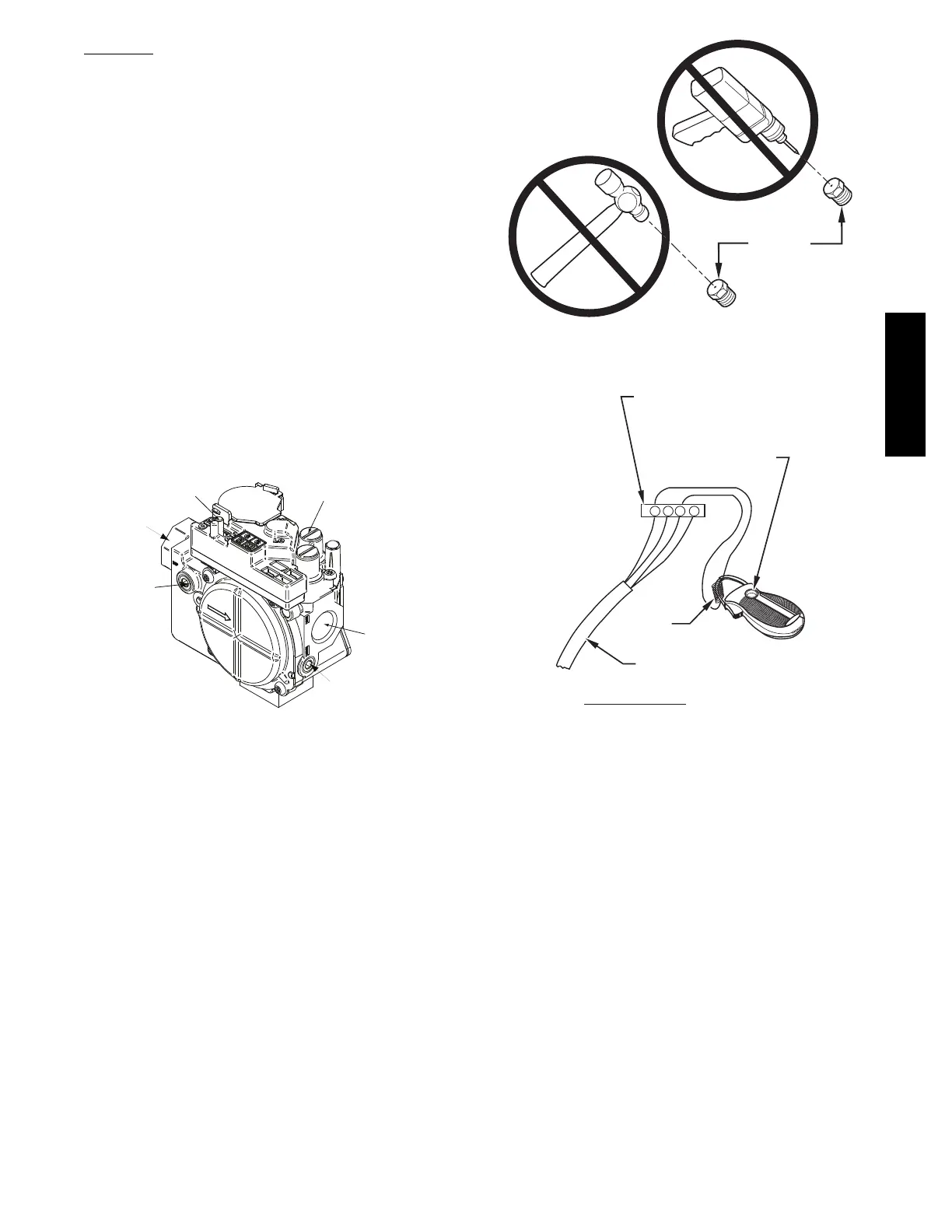
R Y W G
10 TURNS
THERMOSTAT SUBBASE
TERMINALS WITH
THERMOSTAT REMOVED
(ANITICIPATOR, CLOCK, ETC.,
MUST BE OUT OF CIRCUIT.)
HOOK-AROUND
AMMETER
EXAMPLE:
5.0 AMPS ON AMMETER
10 TURNS AROUND JAWS
=
0.5 AMPS FOR THERMOSTAT
ANTICIPATOR SETTING
FROM UNIT 24-V
CONTROL TERMINALS
A96316
Fig. 59 -- Amp. Draw Check with Ammeter
925TA