36
Thermostats
A single stage heating and cooling thermostat can be used with the
furnace. The furnace control board CPU will control the furnace
and outdoor unit staging. A two stage heating and cooling
thermostat can also be used to control the staging. For two stage
thermostat control of the furnace staging, turn SW1-LHT ON at the
furnace control board. For two stage thermostat control of a 2-stage
outdoor unit, remove the ACRDJ jumper from the furnace control
board. Refer to typical thermostat wiring diagrams and the
Sequence of Operation section for additional details. Consult the
thermostat installation instructions for specific information about
configuring the thermostat. See Fig. 36 and 37.
Accessories (See Fig. 34 and 36.)
1. Electronic Air Cleaner (EAC)
Connect an accessory Electronic Air Cleaner (if used) using
1/4--in. female quick connect terminals to the two male
1/4--in. quick--connect terminals on the control board
marked EAC--1 and EAC--2. The terminals are rated for
115VAC, 1.0 amps maximum and are energized during
blower motor operation.
2. Humidifier (HUM)
The HUM terminal is a 24 VAC output, energized when the gas
valve relay is operating during a call for heat.
Connect an accessory 24 VAC, 0.5 amp. maximum humidifier (if
used) to the ¼--in. male quick--connect HUM terminal and
COM--24V screw terminal on the control board thermostat strip.
NOTE: If the humidifier has its own 24 VAC power supply, an
isolation relay may be required. Connect the 24 VAC coil of the
isolation relay to the HUM and COM/24V screw terminal on the
control board thermostat strip. See Fig. 34.
Alternate Power Supplies
This furnace is designed to operate on utility generated power
which has a smooth sinusoidal waveform. If the furnace is to be
operated on a generator or other alternate power supply, the
alternate power supply must produce a smooth sinusoidal
waveform for compatibility with the furnace electronics. The
alternate power supply must generate the same voltage, phase, and
frequency (Hz) as shown in Table 11 or the furnace rating plate.
Power from an alternate power supply that is non-sinusoidal may
damage the furnace electronics or cause erratic operation.
Contact the alternate power supply manufacturer for specifications
and details.
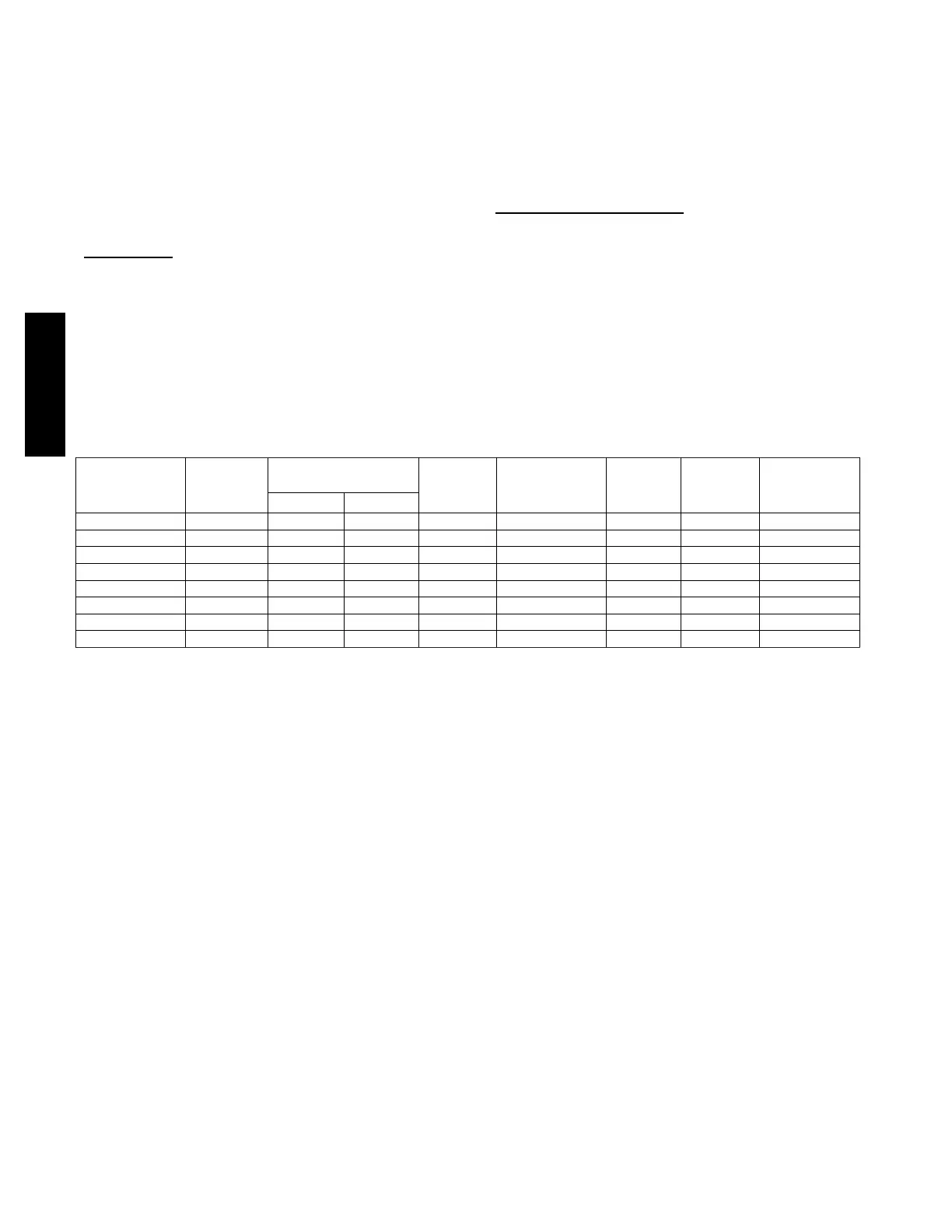
Table 11 – Electrical Data
UNIT SIZE
V O LT S ---
H E R T Z ---
PHASE
OPERATING VOLTAGE
RANGE*
MAXIMUM
UNIT
AMPS
UNIT
AMPACITY#
MINIMUM
WIRE
SIZE
AWG
MAXIMUM
WIRE
LENGTH
FT (M)}
MAXIMUM
FUSE OR CKT
BKR
AMPS{
Maximum* Minimum*
30040 1 1 5 --- 6 0 --- 1 127 104 7.5 10.3 14 36 (11.0) 15
36040 1 1 5 --- 6 0 --- 1 127 104 7.5 10.3 14 36 (11.0) 15
36060 1 1 5 --- 6 0 --- 1 127 104 7.6 10.4 14 35 (10.7) 15
42060 1 1 5 --- 6 0 --- 1 127 104 10.7 14.3 14 26 (7.9) 15
48080 1 1 5 --- 6 0 --- 1 127 104 10.1 13.5 14 27 (8.2) 15
60080 1 1 5 --- 6 0 --- 1 127 104 13.1 17.3 12 33 (10.1) 20
60100 1 1 5 --- 6 0 --- 1 127 104 13.5 17.7 12 32 (9.8) 20
66120 1 1 5 --- 6 0 --- 1 127 104 12.0 15.9 12 36 (11.0) 20
* Permissible limits of the voltage range at which the unit operates satisfactorily.
# Unit ampacity = 125 percent of largest operating component’s full load amps plus 100 percent of all other potential operating components’ (EAC, humidifier,
etc.) ful l load amps.
{Time---delay type is recommended.
}Length shown is as measured one way along wire path between furnace and service panel for maximum 2 percent voltage drop.
925TA
 Loading...


