12
CONDENSATE TRAP
Condensate Trap -- Upflow Orientation
When the furnace is installed in the upflow position, it is not
necessary to relocate the condensate trap or associated tubing.
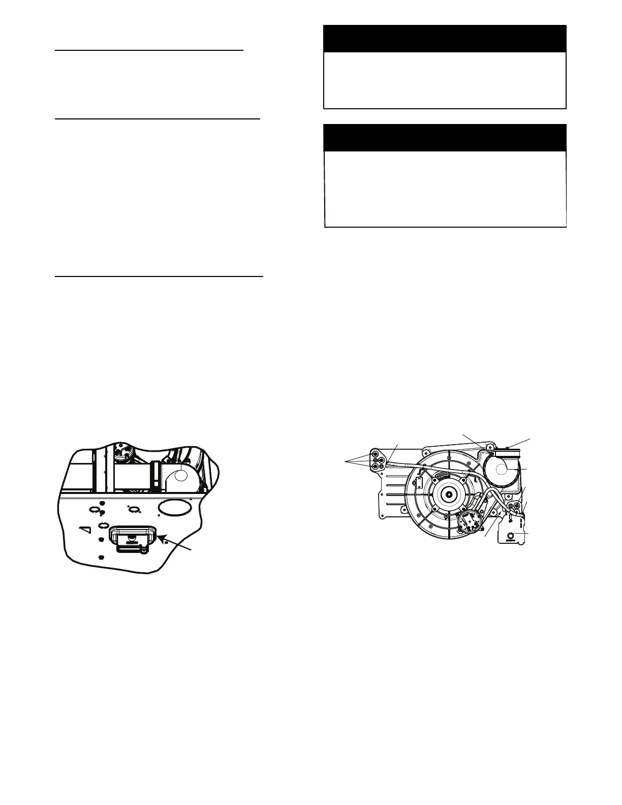
Refer to Fig. 9 for upflow condensate trap information. Refer to
Condensate Drain section for informatio n how to install the
condensate drain.
Condensate Trap -- Downflow Orientation.
When the furnace is installed in the downflow position, the
condensate trap will be initially located at the upper left corner of
the collector box, as received from the factory. See the top image
in Fig. 10. When the furnace is installed in the downflow
orientation, the condensate trap must be relocated for proper
condensate drainage. See the bottom image in Fig. 10.
To Relocate the Condensate Trap:
S Ori ent the fur nace in the downf l ow posi ti on.
S Fig. 10 shows the conde nsate trap and tubing before and after
reloca tion. Refer to Fig. 10 to begin the trap conversion.
S Refer to Condensate Dra i n se c tion for inf or m at i on how to ins ta l l the
condensate drain.
Condensate Trap -- Horizontal Orientation.
Whe n the furnace is inst al l ed in the hor i zontal right posi tion, the
condensate tr ap wi l l be initially located at the bottom of the collector
box, a s received from the factory. See the top image in Fig. 11.
When the furnace is installed in the horizontal left position, the
condensate trap will be initially located at the top of the collector box,
as received from the factory . See the top image in Fig. 12. In both
cases the tr ap must be repositioned on the colle ctor box for prope r
condensate dr ainage. See the bott om images in Fig. 11 and 12.
A field--supplied, accessory Horizontal Installation Kit (trap
grom met) i s required f or al l direct--vent hor iz ont al ins talla ti ons (only).
The kit contains a rubbe r ca sing grommet de signed t o se al between
the furnace ca sing a nd the condensate t rap. See Fi g. 8.
Remove knockout.
Install grommet before
relocating condensate
trap.
NOTE: Trap grommet is required only for direct-vent
applications.
A11582
Fig. 8 -- Horizontal Drain Trap Grommet
The field--supplied, accessory horizontal drain trap grommet is
ONLY REQUIRED FOR DIRECT VENT APPLICATIONS.
It it NOT required for applications using single--pipe or
ventilated combustion air venting.
NOTICE
The condensate trap extends below the side of the casing in
the horizontal position. A minimum of 2-- in. (51 mm) of
clearance is required between the casing side and the furnace
platform for the trap to extend out of the casing in the
horizontal position. Allow at least 1/4--in. per foot (20 mm
per meter) of slope down.
NOTICE
To Relocate the Condensate Trap:
S Remove the knockout in the ca s ing f or the condensate tra p.
S Install the gromme t in the ca sing when required for direct--vent
horiz onta l applicat i ons.
S Orient the furnace in the desired position.
S All ow for 2 in. (51 mm) of clearance underneath the furnace for the
condensate tr ap and dr ain li ne.
S Fig. 11 show s the condensate tr ap and t ubing before and after
relocation in the hori zontal right posi tion.
S Fig. 12 shows the conde nsate trap and tubing before and after
relocation in the hori zontal left position.
S Refer to the appropri a te fi gure to be gi n the trap conve r sion.
S Refer to Condensate Dra i n se c tion for inf or m at i on how to ins ta l l the
condensate drain.
Condensate Trap
Relief Port
Collector Box
Plugs
Pressure Switch
Port
Condensate Trap
Outlet
Condensate Trap
Relief Port
Collector Box
Plug
Vent Elbow
Vent Elbow Clamp
Vent Pipe Clamp
UPFLOW TRAP CONFIGURATION
1 & 2 Stage Units
A11307
Fig. 9 -- Upflo w Trap Configuration
(Appearance may vary)