24
Air Filter Located in Filter Cabinet
FILTER
CABINET
HEIGHT
IN (MM)
F I LT E R S I Z E --- I N ( M M ) FILTE R TYPE
14--- 3/16{
(360)
14 x 25 x 3/4
(356 x 635 x 19)
Washable
or Media*
16 (406)
(1) 16 x 25 x 3/4*
(406 x 635 x 19) or
(1) 16 x 25 x 4---5/16
(406 x 635 x 110)
Washable
or Media*
21 (533)
(1) 20 x 25 x 3/4*
(508 x 635 x 19) or
(1) 20 x 25 x 4---5/16
(508 x 635 x 110)
Washable
or Media*
24 ½ (622)
(1) 24 x 25 x 3/4*or
(610 x 635 x 19) or
(1) 24 x 25 x 4---5/16
(610 x 635 x 110)
Washable
or Media*
* Filters with a side return--- air may have a different filter size. Measure the
filter to obtain the correct size.
* Recommended to maintain air filter face velocity. See Product Data for
part number.
{ Not all families have these models.
EXAMPLE FOR
UPFLOW INSTALLATIONS.
MAY BE APPLIED TO
OTHER CONFIGURATIONS.
A12220
Fig. 29 -- Sample Inlet Air Pipe Connection for Polypr opylene
Venting Systems
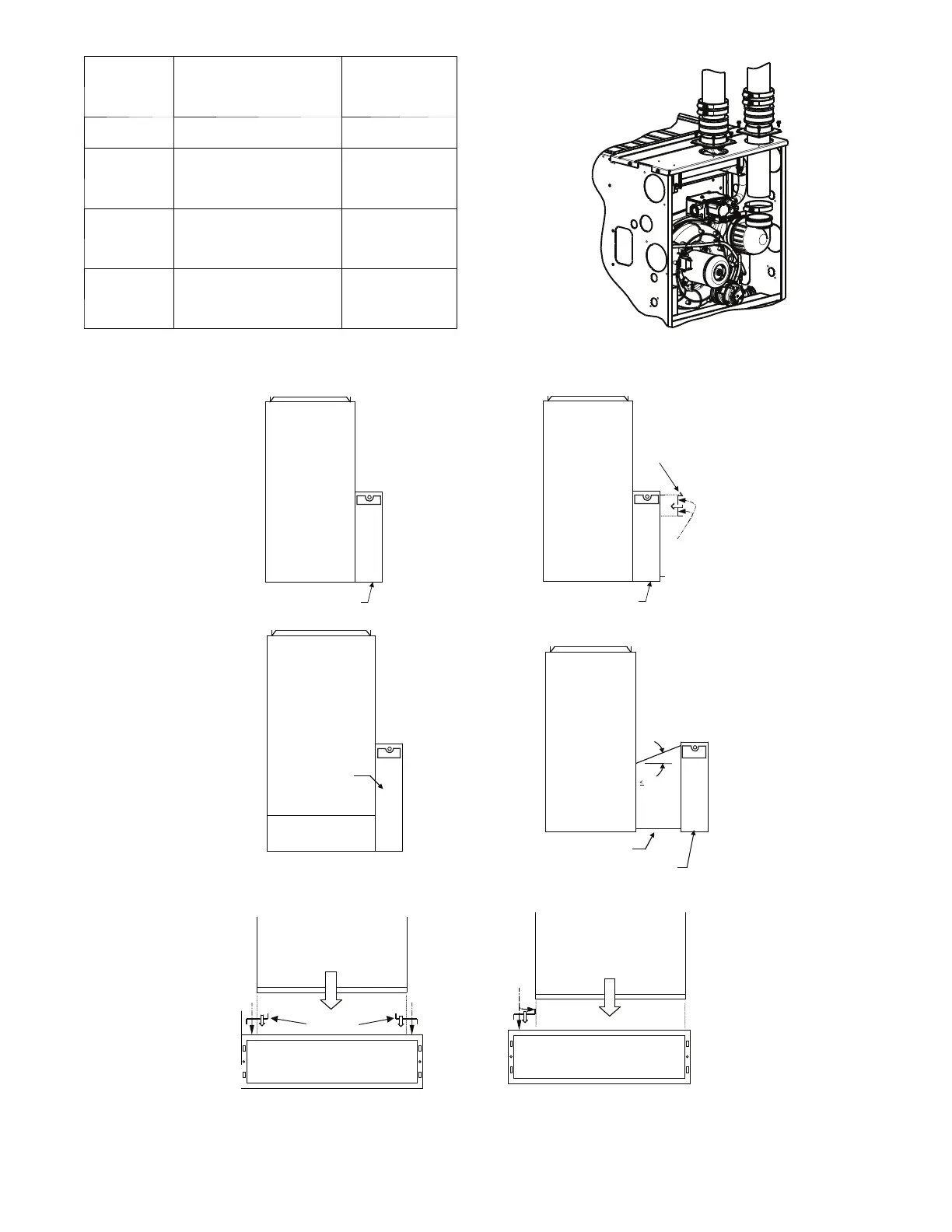
14-3/16 and 17-1/2-in.
Furnace
16-in. Media Cabinet
21-in. Furnace
4-Ton or less, AC
capacity airflow
20-in. Media Cabinet
4-in.
Block Off
Plate
1/2-in.
Screws
20- or 24-in. Media
Cabinet
Bottom Return Plenum
21- or 24-1/2-in.
Furnace
Up to 5-Ton AC
capacity airflow
45°
Transition
20- or 24-in. Media Cabinet
Screw
14-3/16-in. Furnace
Filler plates
Screw
14--3/16-in. Furnace with Filler Plates, Centered
14-3/16-in. Furnace
Filler plate
Screws
14--3/16-in. Furnace with Filler Plates, Off--Set to Right
Media Cabinet Installation Option for
4-Ton or Less A/C Capacity
20- or -24-in. Media Cabinet Installation
with Angled Transition
20- or -24-in. Media Cabinet Installation
for Combination Side and Bottom Return
Media Cabinet Installation
Side Return
21-in. Furnace
up to 5-Ton AC
Capacity
24-1/2-in. Furnace
up to 4-Ton AC
Capacity
A11437
Fig. 30 -- Optional Media Filter