31
NOTE: Use a back -- up wrench on the inlet of the gas valve when
connecting the gas line to the gas valve.
In the state of Massachusetts:
1. Gas supply connections MUST be performed by a licensed
plumber or gas fitter.
2. When flexible connectors are used, the maximum length
shall not exceed 36 in. (915 mm).
3. When lever handle type manual equipment shutoff valves
are used, they shall be T -- handle valves.
4. The use of copper tubing for gas piping is NOT approved
by the state of Massachusetts.
NOTICE
Refer to Table 10 for recommended gas pipe sizing. Risers must be
used to connect to furnace and to meter. Support all gas piping
with appropriate straps, hangers, etc. Use a minimum of one hanger
every 6 ft. (2 M). Joint compound (pipe dope) should be applied
sparingly and only to male threads of joints. Pipe dope must be
resistant to the action of propane gas.
Table 10 – Maximum Capacity of Pipe
NOMINAL
IRON PIPE
SIZE
IN. (MM)
LENGTH OF PIPE --- FT (M)
10
(3.0)
20
(6.0)
30
(9.1)
40
(12.1)
50
(15.2)
1/2 (13) 175 120 97 82 73
3/4 (19) 360 250 200 170 151
1 ( 25) 680 465 375 320 285
1-1/4 (32) 1400 950 770 660 580
1-1/2 (39) 2100 1460 1180 990 900
* Cubic ft of gas per hr for gas pressures of 0.5 psig (14--- In. W.C.) or less and
a pressure drop of 0.5 --- In. W.C. (based on a 0.60 specific gravity gas). Ref:
Table 10 above and 6.2 of current edition of NFPA54/ANSI Z223.1.
FIRE OR EXPLOSION HAZARD
A failure to follow this warning could result in personal
injury, death, and/or property damage.
If local codes allow the use of a flexible gas appliance
connector, always use a new listed connector. Do not use a
connector which has previously served another gas
appliance. Black iron pipe shall be installed at the furnace
gas control valve and extend a minimum of 2-- in. (51 mm)
outside the furnace.
!
WARNING
FURNACE DAMAGE HAZARD
Failure to follow this caution may result in furnace damage.
Connect gas pipe to furnace using a backup wrench to
avoid damaging gas controls and burner misalignment.
CAUTION
!
An accessible manual equipment shutof f valve MUST be installed
external to furnace casing and within 6 ft. (2 M) of furnace.
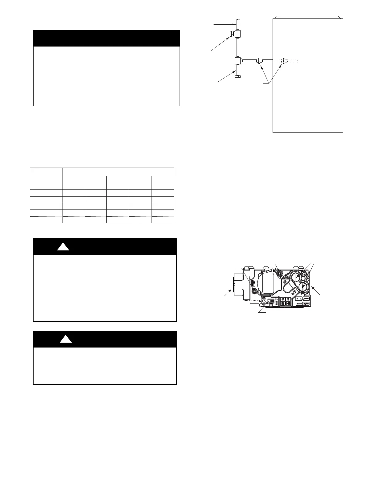
Install a sediment trap externally in the riser leading to furnace as
shown in Fig. 32. Connect a capped nipple into lower end of tee.
Capped nipple should extend below level of furnace gas controls.
Place a ground joint union between furnace gas control valve and
exterior manual equipment gas shutoff valve.
GAS
SUPPLY
MANUAL
SHUT OFF
VALVE
(REQUIRED)
SEDIMENT
TRAP
UNION
NOTE: Union may be inside the
vestibule where permitted by
local codes.
FRONT
A11035
Fig. 32 -- Typical Gas Pipe Arrangement
A 1/8-- in. (3 mm) NPT plugged tapping, accessible for test gauge
connection, MUST be installed immediately upstream of gas
supply connection to furnace and downstream of manual
equipment shutoff valve.
Piping should be pressure and leak tested in accordance with the
current addition of the NFGC in the United States, local, and
national plumbing and gas codes before the furnace has been
connected. Refer to current edition of NSCNGPIC in Canada.
After all connections have been made, purge lines and check for
leakage at furnace prior to operating furnace.
NOTE: The furnace gas control valve inlet pressure tap
connection is suitable to use as test gauge connection providing
test pressure DOES NOT exceed maximum 0.5 psig (14--In. W.C.)
stated on gas control valve. See Fig. 33.
INLET PRESSURE TAP
SET SCREW: 3/32” HEX HEAD
ACCEPTS 5/16” HOSE
CONNECTION
ON/OFF SWITCH
MANIFOLD PRESSURE TAP SET SCREW:
3/32” HEX HEAD ACCEPTS
5/16” HOSE CONNECTION
REGULATOR SEAL CAP
(REGULAR ADJ. UNDER CAP)
OUTP
1/2” NPT
INLET
1/2” NPT
OUTLET
Representative drawing only, some models may vary in appearance.
A170117
Fig. 33 -- Gas Valve with Tower Pressure Ports
If pressure exceeds 0.5 psig (14--In. W.C.), gas supply pipe must be
disconnected from furnace and capped before and during supply
pipe pressure test. If test pressure is equal to or less than 0.5 psig
(14-- In. W.C.), turn off electric shutoff switch located on furnace
gas control valve and accessible manual equipment shutof f valve
before and during supply pipe pressure test. After all connections
have been made, purge lines and check for leakage at furnace prior
to operating furnace.
The gas supply pressure shall be within the maximum and
minimum inlet supply pressures marked on the rating plate with
the furnace burners ON and OFF.
Gas entry can be from left or right side, or top panel. See Figs. 34
and 35.