191VAN Evolution™ Extreme Variable Speed Air Conditioner: Installation Instructions
Manufacturer reserves the right to change, at any time, specifications and designs without notice and without obligations.
16
Amber Status Light
The operation modes and meaning for each mode of the status light is
described in the table below for PCM SW versions 1.0 and above.
5x7 LED Matrix
The Primary Control Module (PCM) is equipped with a 5x7 LED
matrix. This matrix will display the 4 highest priority diagnostic codes
in a scrolling fashion with 2 seconds in between each code. At the end
of the 4th highest priority diagnostic code there is a 5 second pause
before the list repeats.
VFD Communications Light
The PCM is equipped with a bi-color LED for indicating successful or
unsuccessful communication with the VFD. This LED is located just
below the VFD-PCM communication port on the PCM. The LED will
flash green when good messages are received from the VFD and red
when bad or no messages are received from the VFD.
Bluetooth® Module
This unit is equipped with a module, which includes Bluetooth wireless
technology that allows a user to connect via an application on a phone or
tablet. It is recommended that the Bluetooth Module be activated during
the installation process.
Follow these steps to download and activate Bluetooth Module:
1. Download the app
– Search the App Store™ or Google Play™ for Bryant Service
Technician to download. The app is available on phone and tablet
devices. If you already have the app downloaded, please ensure
you have updated to latest version.
To Activate Bluetooth Module:
1. Login to the Bryant Service Technician app using your
HVACPartners user name and password.
2. On the App Home screen, tap the Connect to Equipment button.
Please ensure your equipment is powered on and your mobile
device is within 10 feet of the equipment throughout this whole
process
NOTE: In order to connect to equipment using Bluetooth, you must
have Bluetooth enabled on your mobile device, and you must allow the
Service Tech app to access Bluetooth and location services in your
device permissions. For more information on how to enable these
features and permissions, please consult documentation from your
device manufacturer.
3. The app will scan for nearby Bluetooth enabled equipment. To
activate a new unit, the app will display "New Equipment". Tap on
that item and then select the Pair button
4. The app will display the equipment Serial and Model number.
Please confirm these are correct for the equipment you are trying to
activate and tap continue.
5. The app will now automatically progress through the activation
process. Once the steps are complete, the unit is activated
successfully and your device will be automatically paired to the
equipment.
NOTE: You will only have to perform this activation once and you will
now be able to pair to this equipment directly with the app in the future.
Variable Frequency Drive (VFD)
The VFD or variable frequency drive is located inside the control box.
This is an air-cooled device that communicates with the PCM and drives
the compressor to the demanded RPM. The VFD provides DC voltage to
the fan motor and sends a fan RPM signal to the electronics on the fan
motor. The VFD changes single-phase line voltage to a 3-phase output
that varies in both voltage and frequency to drive the compressor.
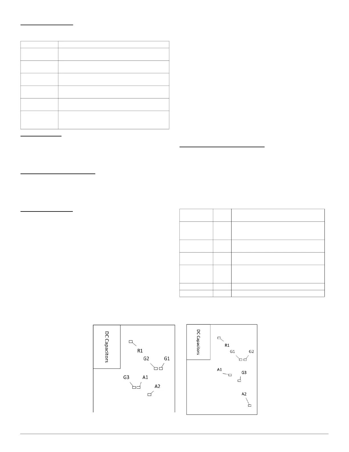
The VFD is equipped with several LEDs that indicate different statuses.
see Table 6 and Fig. 27.
Fig. 27 – VFD LED Indicators
Mode Meaning
Off
Power is removed from the PCM or there is a
fundamental PCM fault.
On
Equipment is in standby with no diagnostic conditions
preventing or limiting operation.
1 Slow Flash
Equipment is operating at low capacity (low stage in
emergency mode).
2 Slow Flashes
Equipment is operating at high capacity (high stage in
emergency mode).
Continuous Slow
Flash
Equipment operation has been interrupted or is being
limited.
Continuous Fast
Flash
Equipment is in a lockout condition as a result of a
diagnostic condition or is in Diagnostic Code Recall
mode.
Table 6 – VFD LED Indicator Functions
LED
Identification
Color Function
R1 Red
Used to indicate that high voltage is present
in the DC capacitors. If this LED is lit then a
DC voltage greater than 40V is present.
G1 Green
Blinks when the VFD receives a message
from PCM.
G2 Green
On when VFD is in normal status. It is off
when VFD is fault status.
G3 Green
On when the VFD micro-controller relay is
closed. The signal of relay is controlled by
PCM.
A1 Amber On when 12V source is normal.
A2 Amber On when the main relay is closed.
HR46VN001 2T VFD
HR46VP003 3T VFD)
4T / 5T VFD