191VAN Evolution™ Extreme Variable Speed Air Conditioner: Installation Instructions
Manufacturer reserves the right to change, at any time, specifications and designs without notice and without obligations.
21
* unlikely to clear on its own; see Service Manual for troubleshooting steps
FINAL CHECKS
IMPORTANT: Before leaving job, be sure to do the following:
1. Ensure that all wiring is routed away from tubing and sheet metal
edges to prevent rub-through or wire pinching.
2. Record final charge on the outdoor unit charging label with
permanent and legible writing.
3. Ensure that all wiring and tubing is secure in unit before adding
panels and covers. Securely fasten all panels and covers.
4. Tighten service valve stem caps to 1/12-turn past finger tight.
5. Re-install red service port caps.
6. Leave Users Manual with owner. Explain system operation and
periodic maintenance requirements outlined in manual.
7. Fill out Dealer Installation Checklist and place in customer file.
REPAIRING REFRIGERANT CIRCUIT
When breaking into the refrigerant circuit to make repairs, or for any
other purpose, the following procedures shall be used.
1. Safely remove the refrigerant using a recovery pump certified for
flammable refrigerants.
2. Purge the refrigerant circuit with an inert gas.
3. Evacuate the refrigerant circuit to 1500 microns.
4. Break vacuum with an inert gas purge of the refrigerant circuit
ensuring that the outlet of the vacuum pump is not near a potential
ignition source.
5. Open the circuit by cutting or brazing.
CARE AND MAINTENANCE
For continuing high performance and to minimize possible equipment
failure, periodic maintenance must be performed on this equipment.
Frequency of maintenance may vary depending upon geographic areas,
such as coastal applications. See Owner's Manual for information.
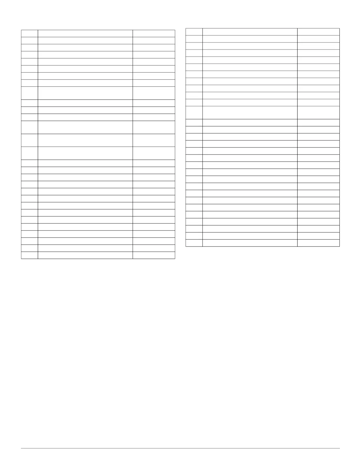
Table 12 – Malfunction Lockout Durations
Code Title Time
13-53 System Control Upgrade Required Permanent
24-58 5V PCM External Power Out of Range Duration of Event
25-61 Invalid Model Plug Malfunction Duration of Event
25-62 Model Plug Missing Malfunction Duration of Event
25-63 VFD Model Mismatch Permanent*
28-71 Fuse 1 Open Malfunction Permanent*
28-72 Fuse 2 Open Malfunction Permanent*
31-58
Compressor High Pressure Limit
Malfunction
2 hours
32-55 Compressor Low Pressure Limit Lockout 2 hours
32-59 Low Pressure Disable Permanent*
33-55 Compressor Low Discharge Limit Lockout 2 hours
34-58
Compressor High Temperature Limit
Malfunction
2 hours
35-58
Compressor High Compression Limit
Malfunction
2 hours
36-55
Compressor Low Compression Limit
Lockout
2 hours
38-53 Compressor Starting Malfunction 4 hours
38-54 Compressor No Pump 30 minutes
38-71 VFD Estimator Malfunction 4 hours
39-53 Fan Start Malfunction 1 hour
39-55 Unexpected Fan Shutdown Malfunction 4 hours
39-58 Fan Motor Malfunction 30 minutes
53-41 OST Open / Low Temp Duration of Event
53-42 OST Shorted / High Temp Duration of Event
57-41 P1 Open Malfunction Duration of Event
57-42 P1 Shorted Malfunction Duration of Event
57-43 P1 Sensor Malfunction Permanent*
58-41 P2 Open Malfunction Duration of Event
58-42 P2 Shorted Malfunction Duration of Event
58-43 P2 Sensor Malfunction Permanent*
61-41 Reversing Valve Solenoid Open Duration of Event
64-41 EXV-H Phase Open Duration of Event
64-44 EXV-H Power Short to Ground Duration of Event
64-45 EXV-H Phase Short to Ground Duration of Event
66-41 VFD Control Relay Coil Open Duration of Event
66-42 VFD Control Relay Coil Shorted Duration of Event
81-53 PFC Malfunction 2 hours
81-54 Unbalanced PFCM Malfunction 4 hours
81-58 VFD System Wiring Error 4 hours
82-53 VFD Reset with Power Dropout Malfunction 2 hours
82-55
VFD Shutdown with Power Dropout
Malfunction
2 hours
82-56 Low Voltage Shutdown Malfunction 2 hours
82-57 Line Over Voltage Malfunction 2 hours
83-55 Compressor Current Limit 3 Lockout 2 hours
83-56 Compressor Current Limit 4 Lockout 2 hours
83-57 Compressor Under-speed Shutdown 1 hour
84-58 VFD Overtemp Malfunction 2 hours
85-53 DC Under Voltage Malfunction 2 hours
85-54 DC Over Voltage Malfunction 1 hour
86-46 VFD Communication Malfunction 1 hour
87-53 VFD Initialization Malfunction 4 hours
88-55 Unexpected VFD Reset Malfunction 2 hours
88-71 VFD Internal Malfunction - Current Sensor 4 hours
88-73 VFD Internal Malfunction - DC Link Sensor 4 hours
88-74 VFD Internal Malfunction - PFCM Sensor A 4 hours
88-75 VFD Internal Malfunction - PFCM Sensor B 4 hours
88-76 VFD Internal Malfunction - Line Volt Sensor 4 hours
88-78 VFD Internal Malfunction - DC Discharge 4 hours
88-79 VFD Internal Malfunction - Microprocessor 4 hours
Table 12 – Malfunction Lockout Durations (Continued)
Code Title Time