191VAN Evolution™ Extreme Variable Speed Air Conditioner: Installation Instructions
Manufacturer reserves the right to change, at any time, specifications and designs without notice and without obligations.
19
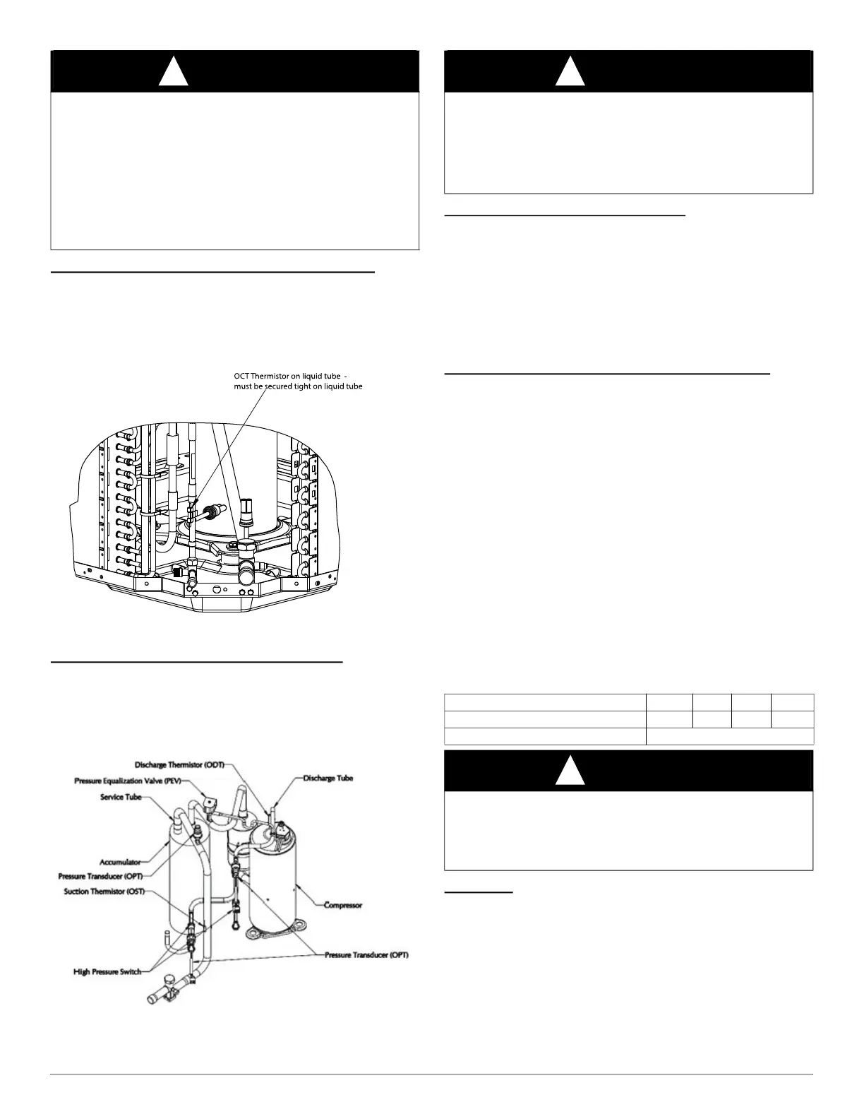
Outdoor Coil / Liquid Line Temperature (LLT-AC)
The LLT-AC is a 10K thermistor used for multiple system operations. It
provides the coil/liquid line temperature to the primary control module
and Evolution™ Connex™ System Control. It is used for subcooling
calculation. The sensor must be securely mounted to the tube connecting
the coil distributor or subcooler to liquid service valve. See Fig. 29 for
proper placement. See Table 8 for proper resistances.
A221569
Fig. 29 – LLT-AC Thermistor Mounted on Coil
Outdoor Discharge Line Temperature (ODT)
The ODT is a 50K thermistor used for protection against over
temperature of the compressor and the discharge superheat calculations.
Proper mounting is required to ensure that the unit exits the start-up
mode and should be inside the compressor sound blanket. (see Fig. 30).
See Table 8 for proper resistances.
A240384
Fig. 30 – ODT Thermistor Mounting Location
Failed Thermistor Default Operation
Factory defaults have been provided in the event of failure of the
Outdoor Air Thermistor (OAT) and/or Liquid Line Thermistor (LLT).
If the OAT sensor should fail the outdoor unit will operate at a fixed
speed. The value of LLT-AC will be substituted for OAT.
If the LLT-AC sensor should fail, the outdoor unit will operate as
expected but subcooling calculation in charging mode will not be
available.
If the OST or ODT should fail, the outdoor unit will continue to operate
as normal.
Variable Speed Compressor Winding Resistance
This compressor operates with 3-phase variable frequency PWM
variable voltage. For troubleshooting certain fault codes related to
compressor resistances, follow these steps:
1. Disconnect compressor power leads from the VFD terminals,
U (YEL), V (RED), and W (BLK).
2. Measure the resistance between YEL to RED, YEL to BLK, and
RED to BLK and compare to Table 10 values. Each resistance set
should be equal.
3. Measure the resistance to ground for each lead.
4. If the resistances are correct then reconnect power leads to
appropriate terminal.
5. If the resistances appear to be abnormal, it will be necessary to
measure the resistance at the compressor fusite terminals.
6. Remove the sound blanket and harness plug, measure the
resistances, and compare to Table 10.
7. Reinstall compressor sound blanket making sure discharge line
thermistor and compressor power harness are routed as they were
from the factory.
Fan Motor
The fan motor requires 5 wires connected to VFD for operation. These
wires are: DC BUS, GND, +15V DC, Vsp, FG. Note high voltage
present on ALL wires because they are not earth or chassis ground
referenced. Do not attempt to measure voltages while running. Fan
speed is monitored by VFD and PCM continuously. If fan faults occur
verify the fan blade rotates freely without obstruction. Ensure all
electrical connections are secure and wires are undamaged.
WARNING
!
PERSONAL INJURY AND/OR PROPERTY DAMAGE
HAZARD
Failure to follow this warning could result in personal injury and/or
property damage.
The appliance shall be stored in a room without continuously operating
ignition sources (for example:
open flames, an operating gas appliance or an operating electric heater.
Do not pierce or burn.
Be aware that refrigerants do not contain an odor.
CAUTION
!
EQUIPMENT DAMAGE HAZARD
Failure to follow this caution may result in equipment damage and/or
improper operation.
In order to minimize the ambient influence, make sure the thermistor
curved surface hugs the pipe surface and is secured tight using the wire
tie fished through the original slot, insulating polymer body.
Table 10 – Variable Speed Compressor Resistances
(winding resistance at 68°F) (20°F)
WINDING 24 36 48 60
Between terminals T1, T2, and T3 1.630 0.740 0.460 0.424
Between terminal & ground >1 mega OHM
CAUTION
!
EQUIPMENT DAMAGE HAZARD
Failure to follow this caution may result in equipment damage and/or
improper operation.
Do not use Meggar for measuring the winding resistance.