BALANCING HRV
Balancing intake and exhaust airflow is very important for proper
system operation and optimum performance when applying an
HRV. Unit balancing prevents a positive and/or negative pressure
within the home. Balancing the HRV is done by applying
temporary flow collars and permanent balancing dampers to the
fresh air intake and stale air exhaust ducts (See Fig. 15 and 16).
Airflow is determined by connecting a magnehelic gage to the
temporary flow collar (See Fig. 17). Both flow collars and
magnehelic gage are included in the accessory start-up balancing
kit.
If supply-air from outside is greater than exhaust-air from the
house, an imbalance can result over pressurizing the home. If
exhaust-air is greater than supply-air, combustion appliances may
backdraft, bringing exhaust fumes into the house. A balanced
condition will ensure optimum performance, provide satisfied
customers, and avoid expensive callbacks.
Before proceeding with balancing, all windows, doors, and fire-
place flues should be tightly closed. No exhaust systems such as
range top exhausts, dryer exhaust, fume hoods, bath or roof fans
should be in operation. The forced-air furnace (if used for
circulation) should be operating in continuous fan mode for normal
operating speed.
I. BALANCING DAMPERS
Balancing dampers (some times called butterfly dampers) are
provided with the HRVBBLHU. The dampers for the HRVBB-
SVU and HRVBBLVU are field supplied and should be perma-
nently located in fresh-air intake and stale-air exhaust ducts
between HRV and exterior wall (See Fig. 15 and 16). Some field
modification may be required to ensure proper installation of
balancing dampers while located in flexible duct. Insulating over
these dampers is strongly recommended after balancing is com-
plete to prevent condensation problems.
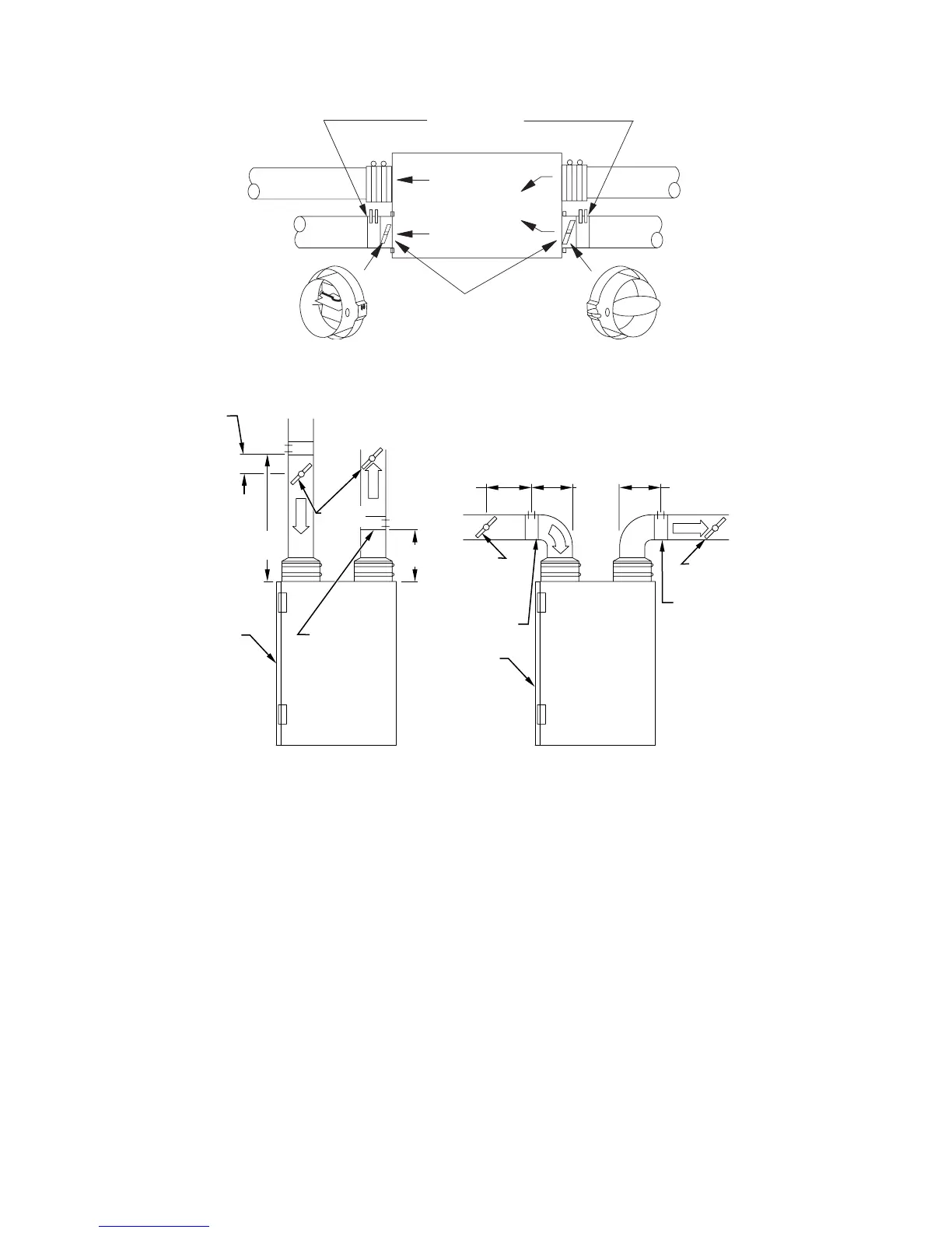
Fig. 15—Balancing HRVBBLHU
A05043
TEMPORARY
FLOW COLLAR
STALE AIR
TO OUTSIDE
FRESH AIR SUPPLY
TO BUILDING
BALANCING
DAMPER
FRESH AIR
FROM OUTSIDE
STALE AIR RETURN
FROM BUILDING
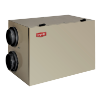
Fig. 16—Balancing HRVBBSVU and HRVBBLVU
A98425
12″
(300mm)
FLOW
COLLAR
FRONT
FRESH AIR
FROM OUTSIDE
STALE AIR
TO OUTSIDE
TEMPORARY
FLOW COLLAR
TEMPORARY
FLOW COLLAR
RIGHT SIDE VIEW RIGHT SIDE VIEW
30″
(760mm)
12″
(300mm)
12″
(300mm)
12″
(300mm)
12″
(300mm)
FRESH AIR
FROM OUTSIDE
STALE AIR
TO OUTSIDE
TEMPORARY
FLOW COLLAR
FRONT
BALANCING
DAMPER
BALANCING
DAMPER
BALANCING
DAMPER
—10—
→