V. WIRING
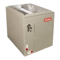
Remove top cover assembly from wall control and pass thermostat
wire through hole located on back of control before attaching to
wall. Connect Y, R, G, and B (yellow, red, green and black)
between wall control and HRV circuit board. Following color code
(See Fig. 11 and 12). Replace top cover assembly.
NOTE: HRV wall control and circuit board operate on 12vdc.
VI. HUMIDITY SELECTOR
The humidity selector is a built-in dehumidistat designed to
properly control the level of humidity in the house during the
winter months. This control helps avoid condensation problems in
upper northern regions where indoor humidity is a problem during
the winter season.
NOTE: This control is not to be confused with a dehumidistat
used during the summer months to control high relative indoor
humidity.
Table 4 recommends humidity levels to avoid condensation.
ELECTRICAL CONNECTIONS
I. 115-VAC WIRING
The HRV operates on 115vac. It comes with a power cord attached
to unit and ready to plug into a fused outlet. Unit must be grounded
for proper operation.
All electrical connections must comply with National and Local
Electrical Codes, or other ordinances that might apply.
WARNING: ELECTRICAL / FIRE HAZARD
Failure to follow this warning could result in property or
unit damage.
Do not use an extension cord as a power source for
operating the HRV.
II. 12-VDC WIRING
The HRV circuit board, wall control, and accessories operate on
12vdc. See Wall Control section, item Wiring and Fig. 11 and 12
for more information.
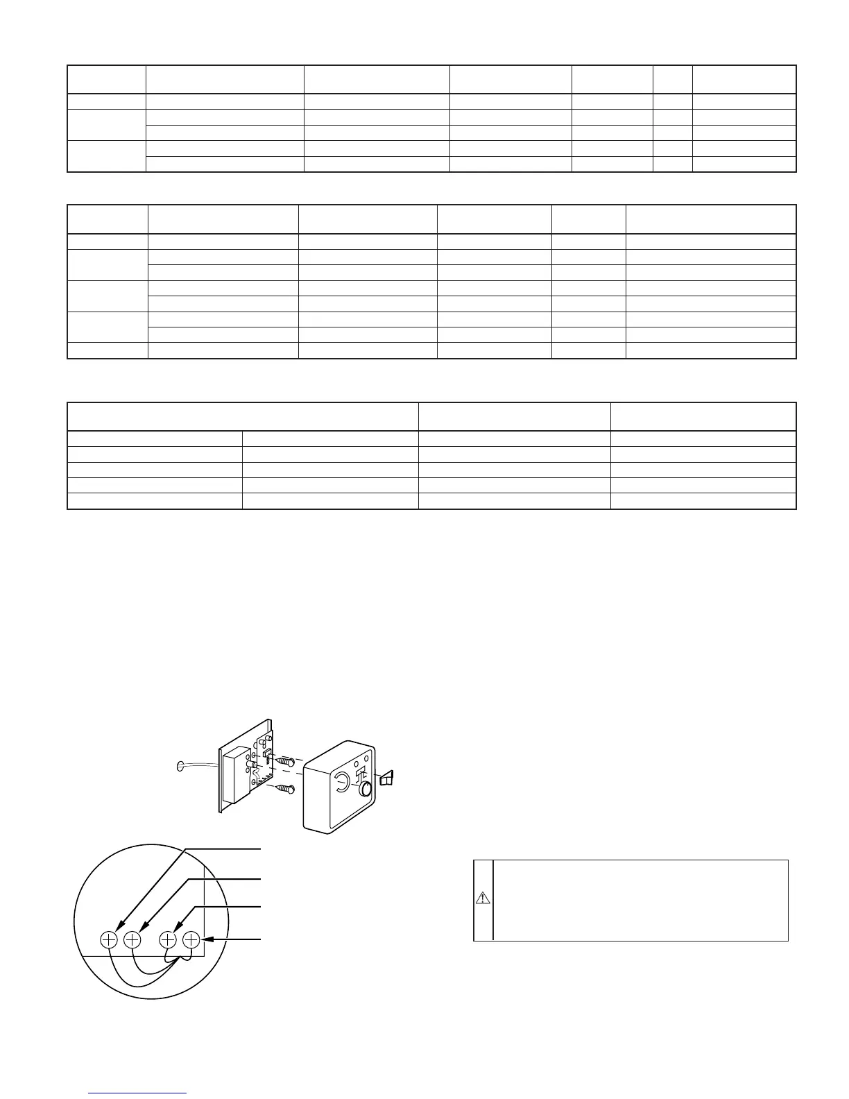
TABLE 2—STANDARD CONTROL
MODE DEHUMIDISTAT POSITION OPERATION DAMPER POSITION FAN SPEED
ON
LED
AIR EXCHANGE
LED
Off Any Off Closed to outside Off Off Off
Low
Satisfied Off Open to outside Low On Off
Call for dehumidification Air exchange with outside Open to outside High On On
Intermittent
Satisfied Air exchange with outside Closed to outside Off On Off
Call for dehumidification Air exchange with outside Open to outside High On On
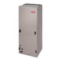
TABLE 3—AUTOMATIC CONTROL
MODE DEHUMIDISTAT POSITION OPERATION DAMPER POSITION FAN SPEED
INDICATOR
LEDS
Off Any Off Closed to outside Off OFF
Intermittent
Satisfied Air exchange with outside Open to outside Off Intermittent ON
Call for dehumidification Air exchange with outside Open to outside High Intermittent and Exchange ON
Continuous
Satisfied Air exchange with outside Open to outside Low Continuous and Exchange ON
Call for dehumidification Air exchange with outside Open to outside High Continuous and Exchange ON
Recirculation
Satisfied Recirculation Closed to outside High Recirculation ON
Call for dehumidification Air exchange with outside Open to outside High Recirculation and Exchange ON
Any Any Any Any Maintenance (open door)
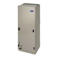
TABLE 4—RECOMMENDED HUMIDITY LEVELS
OUTSIDE TEMPERATURE
DOUBLE-PANE
WINDOWS
TRIPLE-PANE
WINDOWS
50° F 10° C 55 percent 65 percent
32° F 0° C 45 percent 55 percent
14° F -10° C 35 percent 45 percent
-4° F -20° C 30 percent 45 percent
-22° F -30° C 25 percent 35 percent
If the level of humidity falls too low in the winter months while operating in the continuous exchange mode, a humidifier may be integrated into the system. Intermittent
exchange mode may also be selected for short periods of time to increase the level of humidity.
Fig. 11—Typical Wall Control
A98383
YELLOW
YR GB
RED
GREEN
BLACK
—7—