ACCESSORIES
I. INTERLOCK RELAY
The interlock relay kit, Part No. KVAAC0101VIR is required
when installing HRV into a forced-air heating and cooling system
(See Fig. 13). For additional information, refer to Installation
Instructions supplied with interlock relay kit.
The purpose of interlock relay kit is to energize indoor system
equipment (furnace or fan coil) blower whenever HRV is calling.
If HRV is energized, and indoor system equipment is not, interlock
relay will energize and make R and G at indoor equipment. This
will insure fresh air distribution throughout the building via the
central duct system.
II. 20 MINUTE TIMER
A push button timer can be used to override the wall control and
put the HRV into high speed for 20 minutes. Connect switches in
parallel and connect leads to HRV terminals I, OC, and OL (See
Fig. 14). Push button locations are ideal in special activity areas,
such as, bathrooms or kitchen, where high-speed exhaust operation
is needed for a short period of time.
NOTE: The 20 minute timer will not function properly unless
HRV wall control is applied and working correctly. Timing
function is internal to electronic circuit board, it is activated by a
momentary contact between OC and OL. The I connection is to
illuminate the push button. The maximum number of push button
timers that can be applied is 5.
III. 60 MINUTE ADJUSTABLE TIMER
A 60 minute adjustable timer can also be used to override wall
control and put HRV into high-speed operation for a select amount
of time. Connect timer in parallel with push button timers, or to
HRV terminals OC and OL (See Fig. 14).
The 60 minute timer will provide a minimum of 10 minutes, and
a maximum of 60 minutes of ventilation at high speed.
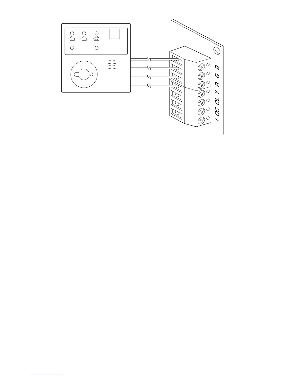
Fig. 12—Control Connections
A98410
% D´HUMIDITE RELATIVE HUMIDITY
´
% HUM. RELATIVE HUM.
55%
45%
35%
30%
EXT. TEMP. EXT.
MODE
MAINTENANCE
AIR EXCHANGE
ECHANGE D´AIR
´
20
25
30
40
50
60
70
80
10°C/50°F
0°C/32°F
–10°C/14°F
–20°C/–4°F
CONTROL
CONNECTOR
WALL CONTROL
YELLOW
RED
GREEN
BLACK
—8—
→