18
Non-Powered Convenience Outlet
This type requires the field installation of a general-purpose 125v
15A circuit powered from a source elsewhere in the building. Ob-
serve national and local codes when selecting wire size, fuse or
breaker requirements, and disconnect switch size and location.
Route 125v power supply conductors into the bottom of the utility
box containing the duplex receptacle.
Unit-Powered Convenience Outlet
A unit-mounted transformer is factory-installed to step down the
main power supply voltage to the unit to 115v at the duplex recep-
tacle. This option also includes a manual switch with fuse, located
in a utility box and mounted on a bracket behind the convenience
outlet; access is through the unit’s control box access panel. See
Fig. 30.
The primary leads to the convenience outlet transformer are not
factory-connected. Selection of primary power source is a custom-
er option. If local codes permit, the transformer primary leads can
be connected at the line-side terminals on the unit-mounted non-
fused disconnect; this will provide service power to the unit when
the unit disconnect switch is open. Other connection methods will
result in the convenience outlet circuit being de-energized when
the unit disconnect is open. See Fig. 32.
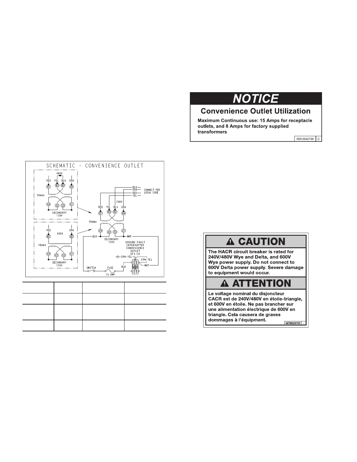
Fig. 32 — Powered Convenience Outlet Wiring
Using Unit-Mounted Convenience Outlets
Units with unit-mounted convenience outlet circuits will often re-
quire that two disconnects be opened to de-energize all power to
the unit. Treat all units as electrically energized until the conve-
nience outlet power is also checked and de-energization is con-
firmed. Observe National Electrical Code Article 210, Branch Cir-
cuits, for use of convenience outlets.
Fuse On Power Type
The factory fuse is a Bussman “Fusetron” T-15, non-renewable
screw-in (Edison base) type plug fuse.
Duty Cycle
The unit-powered convenience outlet has a duty cycle limitation.
The transformer is intended to provide power on an intermittent
basis for service tools, lamps, etc; it is not intended to provide
15-amps loading for continuous duty loads (such as electric heat-
ers for overnight use). Observe a 50% limit on circuit loading
above 8 amps. Convenience outlet usage rating:
• Continuous usage: 8 amps maximum
• Intermittent usage: Up to 15 amps maximum for up to 2
hours maximum. See Fig. 33.
Test the GFCI receptacle by pressing the TEST button on the face
of the receptacle to trip and open the receptacle. Check for proper
grounding wires and power line phasing if the GFCI receptacle
does not trip as required. Press the RESET button to clear the
tripped condition.
Fig. 33 — Convenience Outlet Utilization Notice Label
HACR AMP RATING
The amp rating of the HACR factory-installed option is based on
the size, voltage, indoor motor and other electrical options of the
unit as shipped from the factory. If field-installed accessories are
added or changed in the field (for example, power exhaust,
ERV), the HACR may no longer be of the proper amp rating and
therefore will need to be removed from the unit. See unit name-
plate and label on factory-installed HACR for the amp rating of
the HACR that was shipped with the unit from the factory
(Fig. 34). See unit nameplates for the proper fuse, HACR or
maximum over-current protection device required on the unit
with field-installed accessories.
Fig. 34 — HACR Caution Label
FACTORY-OPTION THRU-BASE CONNECTIONS (ELEC-
TRICAL CONNECTIONS)
This service connection kit consists of a
1
/
2
-in. NPT gas adapter
fitting (brass), a
1
/
2
-in. electrical bulkhead connector, and a
3
/
4
-in.
electrical bulkhead connector, all factory-installed in the embossed
(raised) section of the unit basepan in the condenser section. The
3
/
4
-in. bulkhead connector enables the low-voltage control wires to
pass through the basepan. The
1
/
2
-in. electrical bulkhead connector
allows the high-voltage power wires to pass through the basepan.
See Fig. 18 on page 13.
Check tightness of connector lock nuts before connecting electri-
cal conduits.
Field-supplied and field-installed liquid tight conduit connec-
tors and conduit may be attached to the connectors on the base-
pan. Pull correctly rated high voltage and low voltage through
UNIT
VOLTAGE
CONNECT
AS
PRIMARY
CONNECTIONS
TRANSFORMER
TERMINALS
208, 230 240
L1: RED + YEL
L2: BLU + GRA
H1 + H3
H2 + H4
460 480
L1: RED
Splice BLU + YEL
L2: GRA
H1
H2 + H3
H4
575 600
L1: RED
L2: GRA
H1
H2

 Loading...