20
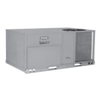
Fig. 36 — Field Control Wiring Raceway
HEAT ANTICIPATOR SETTINGS
Set heat anticipator settings at 0.14 amp for the first stage and 0.14
amp for second-stage heating, when available.
PERFECT HUMIDITY
™
CONTROL CONNECTIONS
Perfect Humidity Space RH Controller
NOTE: The Perfect Humidity system is a factory-installed option
which is only available for units equipped with belt-drive motors.
Perfect Humidity system is not available for single phase (-J volt-
age code) models.
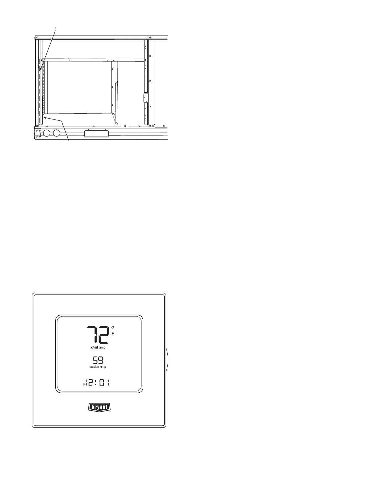
The Perfect Humidity dehumidification system requires a field-
supplied and field-installed space relative humidity control device.
This device may be a separate humidistat control (contact closes
on rise in space RH above control setpoint) or a combination ther-
mostat-humidistat control device such as Bryant’s programmable
thermostat device with isolated contact set for dehumidification
control. See Fig. 37. The humidistat is normally used in applica-
tions where a temperature control is already provided (units with
PremierLink™ control).
Fig. 37 — Programmable Thermostat
Connecting the Field-Supplied Humidistat (HL38MG029)
1. Route the humidistat 2-conductor cable (field-supplied)
through the hole provided in the unit corner post.
2. Feed wires through the raceway built into the corner post
(see Fig. 36) to the 24v barrier located on the left side of
the control box. The raceway provides the UL-required
clearance between high-voltage and low-voltage wiring.
3. Use wire nuts to connect humidistat cable to two PINK
leads in the low-voltage wiring as shown in Fig. 38.
Connecting the Programmable Thermidistat (33CS2PPRH-01)
1. Route the thermostat multi-conductor thermostat cable
(field-supplied) through the hole provided in the unit cor-
ner post.
2. Feed wires through the raceway built into the corner post
(see Fig. 36) to the 24-v barrier located on the left side of
the control box. The raceway provides the UL-required
clearance between high-voltage and low-voltage wiring.
3. The thermostat has dry contacts at terminals D1 and D2
for dehumidification operation (see Fig. 39). The dry con-
tacts must be wired between CTB terminal R and the
PINK lead to the LTLO switch with field-supplied wire
nuts. Refer to the installation instructions included with
the Bryant programmable thermostat device for more
information.
TYPICAL UNIT WIRING DIAGRAMS
See Fig. 38-40 for examples of typical unit control and power wir-
ing diagrams. These wiring diagrams are mounted on the inside of
the unit control box cover.
RACEWAY
HOLE IN END PANEL (HIDDEN)

 Loading...