27
Storage Temperature
–40 to 150°F (–40 to 65°C)
Shipping Temperature
–40 to 150°F (–40 to 65°C)
Relative Humidity
5% to 95% RH non-condensing
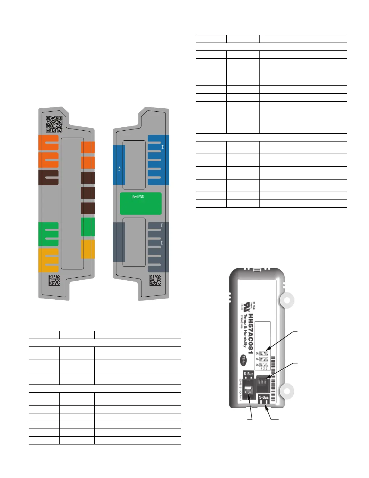
ECONOMIZER MODULE WIRING DETAILS
Use Fig. 45 and Tables 7 and 8 to locate the wiring terminals for
the Economizer module.
NOTE: The four terminal blocks are removable. Slide out each
terminal block, wire it, and then slide it back into place.
Fig. 45 — W7220 Wiring Terminals
Table 7 — Economizer Module - Left Hand Terminal
Blocks
*Sylk is a trademark of Honeywell International Inc.
Table 8 — Economizer Module - Right Hand Terminal
Blocks
S-BUS SENSOR WIRING
The labels on the sensors and controller are color coded for ease of
installation. Orange labeled sensors can only be wired to orange
terminals on the controller. Brown labeled sensors can only be
wired to S-bus (brown) terminals. Use Fig. 46 and Table 9 to lo-
cate the wiring terminals for each S-Bus sensor.
Use Fig. 46 and Table 9 to locate the wiring terminals for each en-
thalpy control sensor.
Fig. 46 — S-Bus Sensor DIP Switches
LABEL TYPE DESCRIPTION
Top Left Terminal Block
MAT
MAT
20k NTC and
COM
Mixed Air Temperature Sensor
(Polarity Insensitive Connection)
OAT
OAT
20k NTC and
COM
Outdoor Air Temperature Sensor
(Polarity Insensitive Connection)
S-BUS
S-BUS
S-BUS (Sylk*
Bus)
Enthalpy Control Sensor
(Polarity Insensitive Connection)
Bottom Left Terminal Block
IAQ 2-10 2-10 vdc
Air Quality Sensor Input (e.g. CO
2
sensor)
IAQ COM COM Air Quality Sensor Common
IAQ 24V 24 vac Air Quality Sensor 24 vac Source
ACT 2-10 2-10 vdc Damper Actuator Output (2-10 vdc)
ACT COM COM Damper Actuator Output Common
ACT 24v 24 vac Damper Actuator 24 vac Source
NA
AUX2-
OCC
E-GND
EXH1
AUX1-O
Y2-
Y1-
Y2-O
Y1-O
C
R
50048848-002
Rev. A
NA
A2
OCC
EX
A1
Y2I
Y2O
Y1I
Y1O
C
R
Cert Product
California Title 24, Part 6
HJW10
www.energy.ca.gov
MAT
MAT
OAT
OAT
S-BUS
S-BUS
IAQ 2-10
IAQ COM
IAQ 24V
ACT 2-10
ACT CO M
ACT 24V
MA
MA
OA
OA
SB
SB
SB
SB
SB
SB
V
C
R
V
C
R
NA
50040839-001
Rev. G
LABEL TYPE DESCRIPTION
Top Right Terminal Blocks
AUX2 I 24 vac IN The first terminal is not used.
OCC 24 vac IN
Shut Down (SD) or HEAT (W)
Conventional only
and
Heat Pump Changeover (O-B) in Heat
Pump mode.
E-GND E-GND Occupied/Unoccupied Input
EXH1 24 vac OUT Exhaust Fan 1 Output
AUX1 O 24 vac OUT
Programmable:
Exhaust fan 2 output
or
ERV
or
System alarm output
Bottom Right Terminal Blocks
Y2-I 24 vac IN
Y2 in - Cooling Stage 2 Input from
space thermostat
Y2-O 24 vac OUT
Y2 out - Cooling Stage 2 Output to
stage 2 mechanical cooling
Y1-I 24 vac IN
Y1 in - Cooling Stage 2 Input from
space thermostat
Y1-O 24 vac OUT
Y1 out - Cooling Stage 2 Output to
stage 2 mechanical cooling
C COM 24 vac Common
R 24 vac 24 vac Power (hot)
DIP
SWITCH
LABEL
DIP
SWITCHES
(3)
S-BUS
2 PIN SIDE
CONNECTOR
S-BUS
TERMINALS
(1 AND 2)

 Loading...