28
Table 9 — HH57AC081 Sensor Wiring Terminations
Use Fig. 46 and Table 10 to set the DIP switches for the desired
use of the sensor.
Table 10 — HH57AC081 Sensor DIP Switch
NOTE: When a S-Bus sensor is connected to an existing network,
it will take 60 minutes for the network to recognize and auto-con-
figure itself to use the new sensor.
During the 60-minute setup period, no alarms for sensor failures
(except SAT) will be issued and no economizing function will be
available.
CO
2
SENSOR WIRING
When using a CO
2
sensor the black and brown common wires are
internally connected and only one is connected to “IAQ COM” on
the W7220. Use the power from the W7220 to power the CO
2
sensor OR make sure the ground for the power supplies are com-
mon. See Fig. 47 for CO
2
sensor wiring.
Fig. 47 — CO
2
Sensor Wiring
INTERFACE OVERVIEW
This section describes how to use the Economizer’s user interface
for:
• Keypad and menu navigation
• Settings and parameter changes
• Menu structure and selection
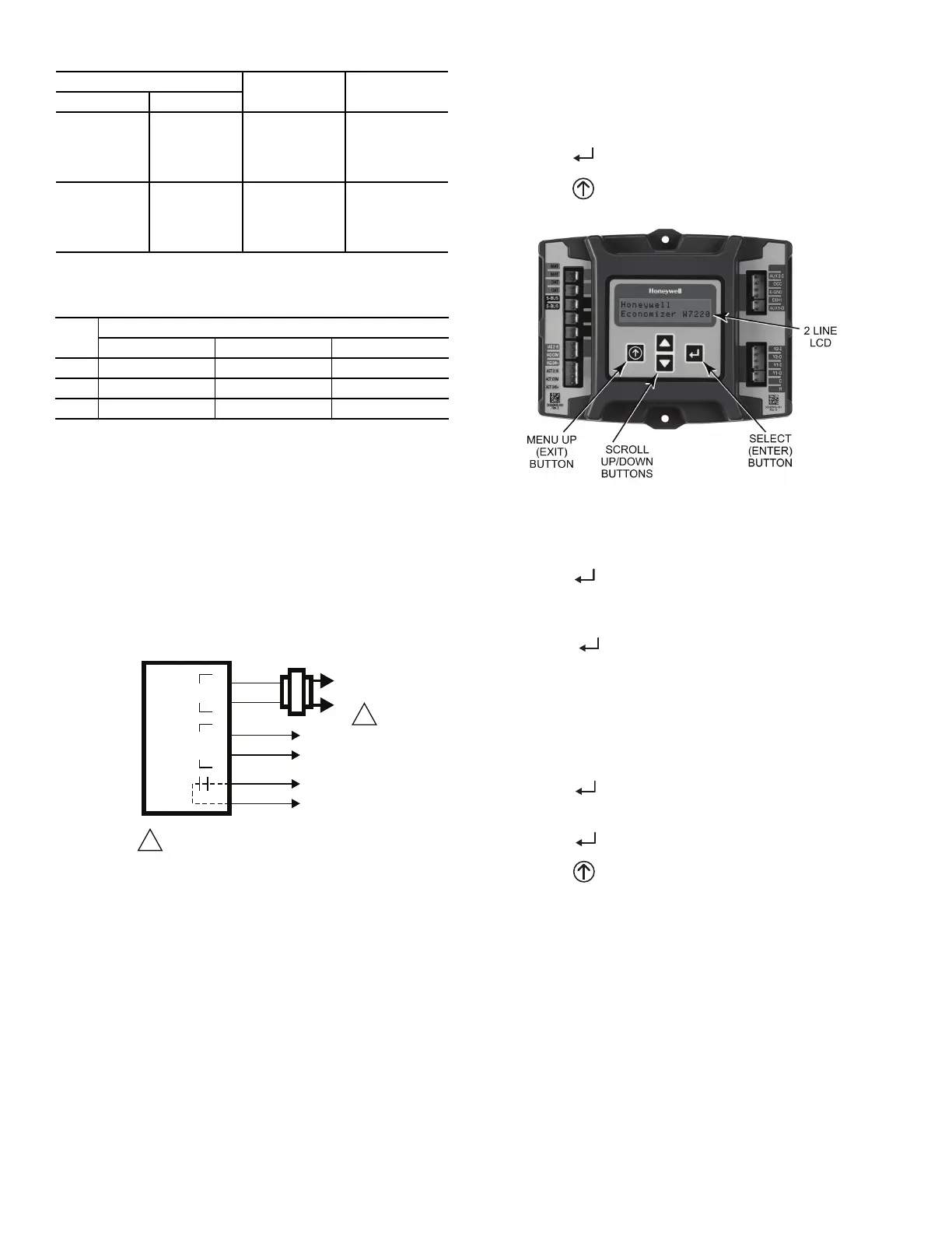
USER INTERFACE
The user interface consists of a 2-line LCD display and a 4-button
keypad on the front of the economizer controller.
KEYPAD
The four navigation buttons (see Fig. 48) are used to scroll
through the menus and menu items, select menu items, and to
change parameter and configuration settings.
To use the keypad when working with menus:
• Press the ▲ (Up arrow) button to move to the previous
menu.
• Press the ▼ (Down arrow) button to move to the next
menu.
• Press the (Enter) button to display the first item in the
currently displayed menu.
• Press the (Menu Up/Exit) button to exit a menu’s item
and return to the list of menus.
Fig. 48 — W7220 Controller Navigation Buttons
To use the keypad when working with Setpoints, System and Ad-
vanced Settings, Checkout tests and Alarms:
1. Navigate to the desired menu.
2. Press the (Enter) button to display the first item in the
currently displayed menu.
3. Use the ▲ and ▼ buttons to scroll to the desired parame-
ter.
4. Press the (Enter) button to display the value of the
currently displayed item.
5. Press the ▲ button to increase (change) the displayed
parameter value.
6. Press the ▼ button to decrease (change) the displayed
parameter value.
NOTE: When values are displayed, pressing and holding the ▲ or
▼ button causes the display to automatically increment.
7. Press the (Enter) button to accept the displayed value
and store it in nonvolatile RAM. “CHANGE STORED”
displays.
8. Press the (Enter) button to return to the current menu
parameter.
9. Press the (Menu Up/Exit) button to return to the previ-
ous menu.
MENU STRUCTURE
Table 11 illustrates the complete hierarchy of menus and parame-
ters for the EconoMi$er
®
X system.
The menus in display order are:
•STATUS
•SETPOINTS
• SYSTEM SETUP
• ADVANCED SETUP
• CHECKOUT
•ALARMS
TERMINAL
TYPE DESCRIPTION
NUMBER LABEL
1 S-BUS S-BUS
S-BUS
Communications
(Enthalpy
Control Sensor
Bus)
2 S-BUS S-BUS
S-BUS
Communications
(Enthalpy
Control Sensor
Bus)
USE
DIP SWITCH POSITIONS FOR SWITCHES 1, 2, AND 3
123
DA OFF ON OFF
RA ON OFF OFF
OA OFF OFF OFF
CO
2
SENSOR
24V
ANALOG
OUT
L1
(HOT)
L2
RED
BLACK
YELLOW
BROWN
ORANGE
GREEN
+
–
POWER SUPPLY. PROVIDE DISCONNECT
MEANS AND OVERLOAD PROTECTION
AS REQUIRED.
1
1
 Loading...