12
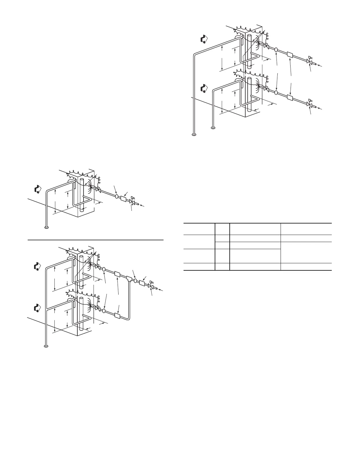
In some applications, depending on space and convenience re-
quirements, it may be desirable to install 2 filter driers and
sight glasses in a single circuit application. One filter drier and
sight glass may be installed at A locations (see Fig. 9) or 2 fil-
ter driers and sight glasses may be installed at B locations (see
Fig. 9 and 10).
Select the filter drier for maximum unit capacity and minimum
pressure drop. Complete the refrigerant piping from the indoor
unit to the outdoor unit before opening the liquid and suction
lines at the outdoor unit.
INSTALL LIQUID LINE SOLENOID VALVE
It is recommended that a solenoid valve be placed in the main
liquid line (see Fig. 9 and 10) between the condensing unit and
the evaporator coil. Locate the solenoid valve at the outlet end
of the liquid line, near the evaporator coil connections, with
flow direction arrow pointed at the evaporator coil. Refer to
Table 13. (A liquid line solenoid valve is required when the liq-
uid line length exceeds 75 ft [23 m].) This valve prevents re-
frigerant migration (which causes oil dilution) to the compres-
sor during the off cycle, at low outdoor ambient temperatures.
Wire the solenoid in parallel with the compressor contactor coil
(see Fig. 9 and 10). This means of electrical control is referred
to as solenoid drop control.
Fig. 9 — Location of Sight Glass(es) and Filter Driers
Typical 569J***A/B/G/H Systems
Fig. 10 — Location of Sight Glasses and Filter Driers
Typical 569J***D/E/F Systems
Solenoid Drop Control Wiring
Control the power to the liquid line solenoid through a Sole-
noid Valve Relay (SVR) in all units. Use part number
HN61PC005 (field-supplied, installed). 569J***A/B/G/H unit
requires one SVR; 569J***D/E/F unit requires two relays.
A unit with two liquid line solenoid valves also requires a sep-
arate control power transformer for the liquid solenoid valve
loads. Select TRAN3 transformer part number according to
unit power supply.
LEGEND
* Install as SVR-2 (SVR-1 is factory-installed).
Mount the SVR (and transformer TRAN3 when used) in unit
control box. Connect per wiring schematic label on unit.
NOTE: TRAN3 is provided with the HGBP factory installed op-
tion for 569J*12F units.
INDOOR
COIL CKT 2
AIRFLOW
INDOOR
COIL CKT 1
AIRFLOW
15 DIAMS
MIN
10
DIAMS
8 DIAMS
MIN
TXV
SENSING
BULB
EQUALIZER LINE
SIGHT GLASS
A LOCATION
SIGHT
GLASSES
B LOCATION
TXV
CKT 2
FILTER DRIER
A LOCATION
FILTER
DRIERS
B LOCATION
FLO
W
TXV
SENSING
BULB
TXV
CKT 1
8 DIAMS
MIN
15 DIAMS
MIN
10
DIAMS
SINGLE CIRCUIT COIL PIPING CONFIGURATION
FOR SINGLE COMPRESSOR CONDENSING UNITS
DUAL CIRCUIT COIL PIPING CONFIGURATION
FOR SINGLE COMPRESSOR CONDENSING UNITS
15 DIAMS
MIN
10
DIAMS
8 DIAMS
MIN
INDOOR
COIL CKT
AIRFLOW
TXV
SENSING
BULB
EQUALIZER LINE
SIGHT GLASS
A LOCATION
TXV
FILTER DRIER
A LOCATION
LIQUID LINE
SOLENOID
VALVE
FLOW
LIQUID LINE
SOLENOID
VALVE
MODEL
QTY
LSV
RELAY SVR
QTY - PART NUMBER
TRAN3 PRIMARY V:
PART NUMBER
569J***
A/B/G/H
11 — HN61PC005 N/R
2 2 — HN61PC005 208/230V: HT01BD202
569J***D/E/F 22 — HN61PC005
460V: HT01BD702
575V: HT01BD902
569J*12F 2 1 — HN61PC005* N/R #
LSV — Liquid Solenoid Valve
SVR — Solenoid Valve Relay
N/R — Not Required
N/R # — Not Required / Factory Installed
AIRFLOW
SUCTION
CIRCUIT 2
SUCTION
CIRCUIT 1
AIRFLOW
15 DIAMS
MIN
10
DIAMS
8 DIAMS
MIN
TXV
SENSING
BULB
EQUALIZER LINE
SIGHT
GLASSES
TXV
CKT 2
FILTER
DRIERS
LIQUID LINE
SOLENOID VALVE
CIRCUIT 2
FLOW
LIQUID LINE
SOLENOID VALVE
CIRCUIT 1
FLOW
TXV
SENSING
BULB
TXV
CKT 1
8 DIAMS
MIN
15 DIAMS
MIN
10
DIAMS
DUAL CIRCUIT COIL PIPING CONFIGURATION
FOR TWO CIRCUIT CONDENSING UNITS

 Loading...