6
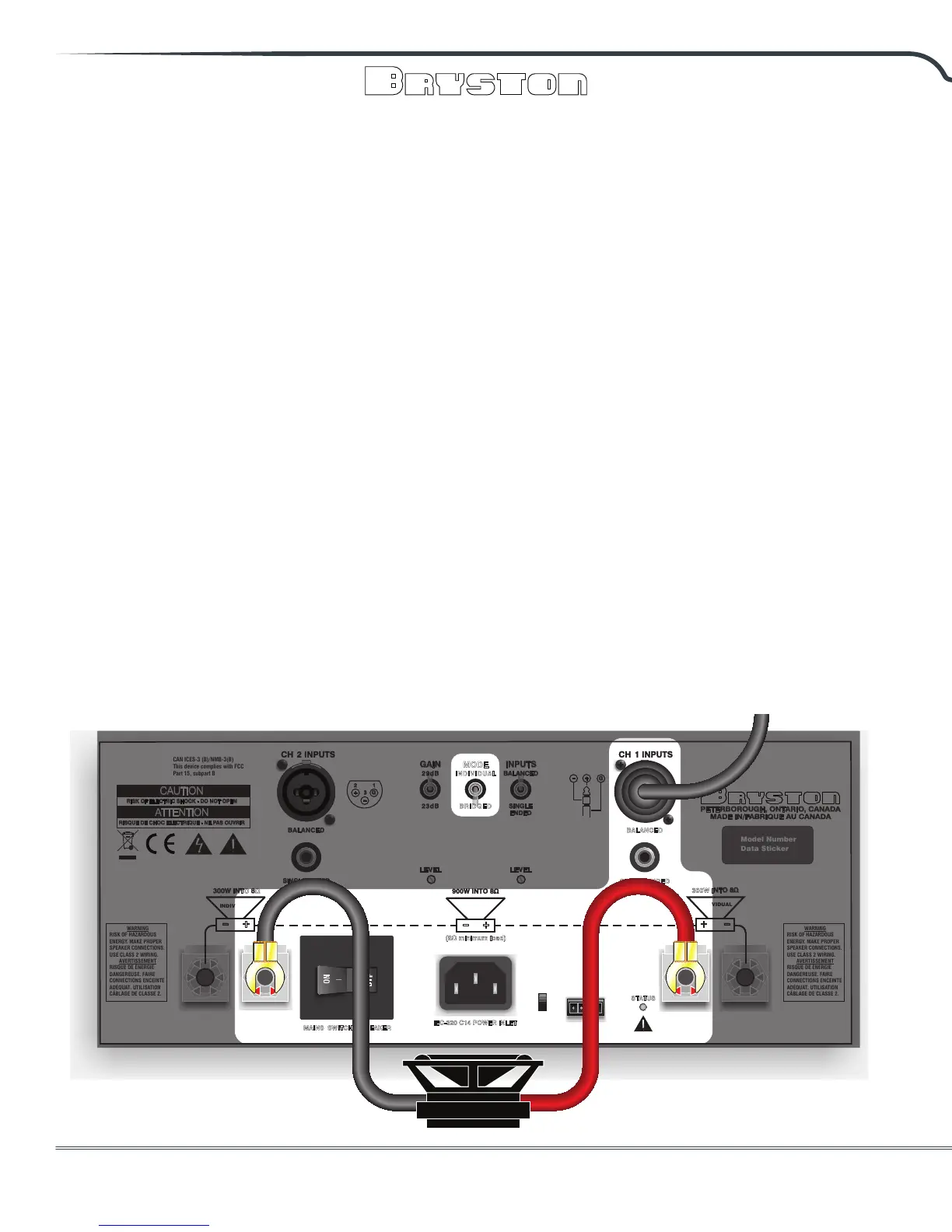
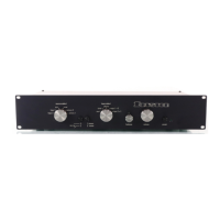
Connecting to Loudspeakers:
Bridged Mode
“Bridged mode” connects the individual channels
in series to form a single amplier channel. The
primary reason for doing this is to achieve a single
amplier channel with much greater output power.
When two 3B
3
channels or two 4B
3
channels are
bridged, the combined single channel will output
up to two times the original voltage and therefore,
theoretically, four times the power of a single
individual channel. In practice, the actual output
power achieved is limited by the capability of the
power supply as well as the ability of the amplier
to dissipate the increased heat that is generated.
It should noted that the usual minimum load
connected to a pair of bridged 3B
3
or 4B
3
channels
should be greater than or equal to 8 Ohms.
To prevent the risk of equipment damage or
personal harm, use only Class 2 rated loudspeaker
wire properly terminated and connected securely to
the binding posts.
Connections are only to be made in areas
highlighted in the diagram below.
• Only Channel #1 input is used.
• The input can be either balanced or un-
balanced.
• Only the two RED binding post connectors
are used (i.e. the BLACK ones are NOT used
and must have nothing connected).
• The Channel 1 RED binding post is the
positive polarity and connected to (+) on
the loudspeaker. Channel 2 RED binding
post connector is negative polarity and
connected to (-) on the loudspeaker.
• The bridged output is oating with respect
to ground. DO NOT CONNECT EITHER
OUTPUT TERMINAL TO GROUND.
• To engage bridged mode, place the MODE
switch, located on the rear panel, into the
BRIDGED position, but before doing so,
make sure all input and output connections
are correct for bridged mode operation.
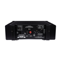
Model Number
Data Sticker
1
2
3
1
2
3
300W INTO 8Ω
3
00W INTO 8Ω
29dB
23dB
MAINS SWITCH & BREAKER
++
--
SINGLE
ENDED
BALANCED
GAIN
+
-
+
_
_
+
3
G
G
2 1
(8Ω minimum load)
INPUTSMODE
INDI V IDUAL
BRID G ED
BALANCED
SINGLE ENDED
STATUS
BALANCED
SINGLE ENDED
PETERBOROUGH, ONTARIO, CANADA
MADE IN/FABRIQUE AU CANADA
IEC-320 C14 POWER INLET
LEVEL
LEVEL
BRIDGED
INDIVIDUAL
INDIVIDUAL
REMOTE POWER-UP
IN
OUT
LOCAL
EXTERNAL
RISK OF ELECTRIC SHOCK - DO NOT OPEN
CAUTION
PRECAUTION
RISQUE DE CHOC ELECTRIQUE - NE PAS OUVRIR
ATTENTION
CAUTION
CAN ICES-3 (B)/NMB-3(B)
This device complies with FCC
Part 15, subpart B
WARNING
RISK OF HAZARDOUS
ENERGY. MAKE PROPER
SPEAKER CONNECTIONS.
USE CLASS 2 WIRING.
AVERTISSEMENT
RISQUE DE ÉNERGIE
DANGEREUSE. FAIRE
CONNECTIONS ENCEINTE
ADÉQUAT. UTILISATION
CÂBLAGE DE CLASSE 2.
WARNING
RISK OF HAZARDOUS
ENERGY. MAKE PROPER
SPEAKER CONNECTIONS.
USE CLASS 2 WIRING.
AVERTISSEMENT
RISQUE DE ÉNERGIE
DANGEREUSE. FAIRE
CONNECTIONS ENCEINTE
ADÉQUAT. UTILISATION
CÂBLAGE DE CLASSE 2.
From Pre-Amp
Speaker (-)
Terminal
Speaker (+)
Terminal