4B
3
& 3B
3
Ampliers
7
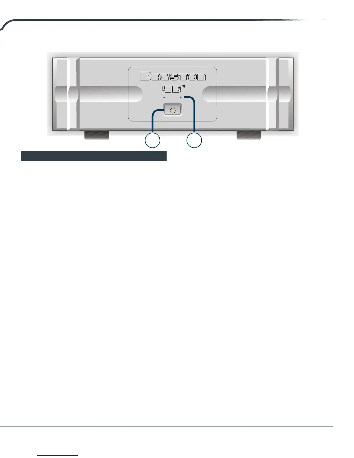
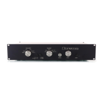
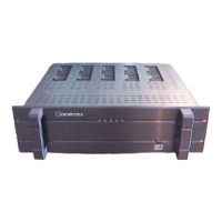
1. Power/Standby Switch:
The front panel features a push-on/push-o
type latching power switch used to apply or
remove A/C line power to the SoStart circuitry.
Note that the rear circuit breaker must be on for
the amplier to power-up.
2. LED Indicators:
Each amplier channel has an LED indicator to
monitor the following conditions:
Unlit Amplier not powered on (OFF
MODE)
Red Channel is muted during power up
Green Channel operation is normal
Flashing
Red
Channel is clipping. Reduce input
level!
Orange Thermal protection mode
POWER UP SEQUENCE
Aer pushing the power switch, each channel
LED will turn from unlit to red (mute). When the
power supplies have stabilized, the channel will
come out of mute and the LED will change to
green (normal operation).
UNLIT LED (No power)
The amplier channel LED when unlit indicates
no A/C mains power is present at the channel
power transformer. If both channel LEDs are
unlit, the amplier probably needs only to be
powered on.
CLIPPING (ashing red)
Clipping occurs when the channel output level
no longer can follow the level increase at the
input (over driven input condition). When a
channel is driven into clipping, the channel
LED will change from green to red then back to
green when the level is reduced. Momentary
clipping can be tolerated, however it indicates
that maximum undistorted power has been
surpassed and potential speaker damage
may result if overload conditions persist. Any
amplier that is constantly operated into
clipping indicates a more powerful amplier is
needed for that application.
THERMAL SHUTDOWN (orange)
Each channel has thermal shutdown circuitry
to prevent damage due to overheating. Should
thermal shutdown occur, the channel will mute,
and the channel LED will turn orange. When
the channel has cooled to a safe operating
condition, the channel will return to normal
operation. Persistent thermal shutdown
indicates steps need to be taken to increase
airow across the channel or channels heat
sink. See “Ventilation” on page 4.
In some markets the LED indicators, which are
normally red/green, may be red/blue instead.
When red/blue LEDs are supplied green is
replaced with blue and orange is replaced with
magenta in the above descriptions.
Front Panel
1 2