4B
3
& 3B
3
Ampliers
9
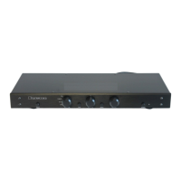
6. Channel Level Attenuators (PRO
ONLY):
The level control will attenuate the input signal
level from 0dB through -14dB.
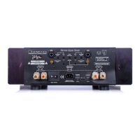
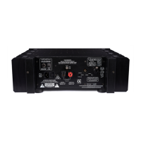
7. Output Binding Posts:
The RED binding post is connected to the
amplier output. Connect to this post the (+)
terminal on the loudspeaker for normal (non-
bridged or individual) operation.
The BLACK binding post is connected to signal
ground. Connect to this post the (-) terminal
on the loudspeaker for normal (non-bridged or
individual) operation.
Only use Class 2 Rated Wiring. No other wiring is
permitted for use.
The output binding posts provide three dierent
interconnect options: banana plugs, spade lugs,
and bare wire. Combinations may be used when
bi-wiring. Cables should be kept as short as
practical and should never be terminated with
connectors that may become confused for AC
power connectors. Cables should be dressed
away from input and power cables.
8. Master Circuit Breaker:
The Cubed series amplier uses a magnetic-
trip circuit breaker to protect the amplier.
This breaker is not an on o switch and must
be in the ‘ON’ position during the installation
and normal operation. Use the front panel
push-button power switch or an external
control voltage to power-up or power-down
the amplier. Should the breaker trip, or switch
“OFF”, lower or remove the amplier input
signals. Remove the AC power by disconnecting
the power cord from the amplier for 20
seconds. Switch the breaker to the ‘ON’ position.
Reconnect the power cord, then power the unit
up normally. The circuit breaker must be ‘ON’
at all times for the Cubed Series amplier to
operate.
9. A/C Power Input:
An IEC-320 C14 power inlet provides for
connection of an IEC-320 C13 equipped power
cord. Before connecting the power cord to the
amplier, check that the voltage rating on the
data plate or ratings label conforms with your
locality. With the circuit breaker ‘ON’ insert the
power cord into the Cubed series amplier, then
plug the other end to an appropriate A/C power
outlet.
10. Remote Power Up:
When in External position, the Power On state
is governed by voltage applied to IN terminals
of the Remote Power Up connector. The front
panel power switch must remain in the ‘ON’
position. “External Control Voltage” on page
5 for instructions regarding connection and
usage.
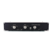
11. Power Status Indicator:
Plugging in the power cord applies power to
the amplier. The status indicator will initially
ash green. The number of ashes indicates the
revision of the so start circuit soware. This
puts the amplier in Standby mode and the LED
turns red indicating power is present.
Engaging the front panel on/o switch initializes
the startup sequence. During the so start ramp
up, operation the status led will turn orange
when connected to 60Hz power or red when
connected to 50Hz power. The Status LED
switches to green when the ramp up sequence
ends. Turning o the front panel on/o switch
returns the amplier to the Standby mode.
12. Data Plate:
Unit specic information is printed here
including model number, operating voltage,
frequency, and serial number.
4B3-17-SIL-120
~120V 60Hz 1000W
Serial No: 4B3-000000
Date: 1530 REV: 1234