38
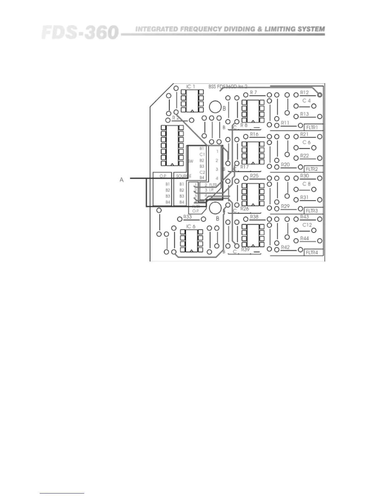
Connection of the filter blocks into the FDS360 frequency bands is arranged
by the wire link strapping between the various connection areas:
Filter I.P : Are the inputs to the filter blocks.
Filter O.P : Are the outputs of the filter blocks.
O.P : Are the band insert returns, and are connected to the Filter O.P.
SOURCE : Are the band insert sends, and are connected to the Filter I.P
Note that the main CHN1 and CHN2 input signals are also provided, as is the
switched send.
Reference to the FDS360 block diagram in section 20.3 will help clarify the
exact position of these signal feeds and insertion points.
FDS 360 D-Card