1 Display panel 2 WAKE UP button 3 Protective box 4 RJ45 port
5 RJ45 port 6 RJ45 port 7 Negative power socket
8 Positive power socket 9 Grounding point 10 Rubber pad
Table 3.3 Description of main components
Display the operating mode, SOC, error code of the
battery
1. DIP switch for setting battery communication
address.
2. Fuse used to protect the main circuit of battery.
For communication with BMS monitor or EMS
For communication with BST, Deye, Goodwe, Sofar,
Solis, Victron, Voltronic and other inverters.
For cascade communication between batteries.
For cascade communication between batteries
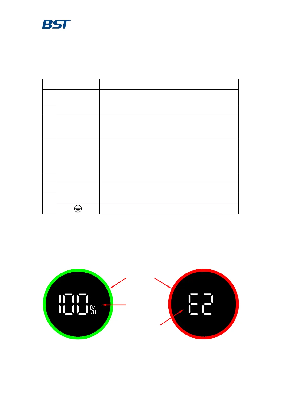
2.3.1 Display Panel
The display panel lights up when the battery is turned on. After 5 minutes, the
display panel will turn off automatically. Press the wake-up button for 1 second
and then release it to make the display panel light up again.
Figure 2.3.1.a Normal state
Figure 2.3.1.b Alarm state