Modules for Logamatic 4000 control panels - We reserve the right to make technical modifications.
15
Module installation for Logamatic 43xx controls 3
When removing and replacing a module
z Loosen all the connectors of the module in question and fix in
park position (for more detailed information, please see the
installation instructions for the Logamatic 43xx control panels).
z Remove module from the control panel.
z Insert the new module by pressing it down from above onto the
sensor strip in the free slot (
Æ Fig. 4, page 14) until it snaps in
audibly.
z Plug sensor cables and pump connections into the places
provided on the module.
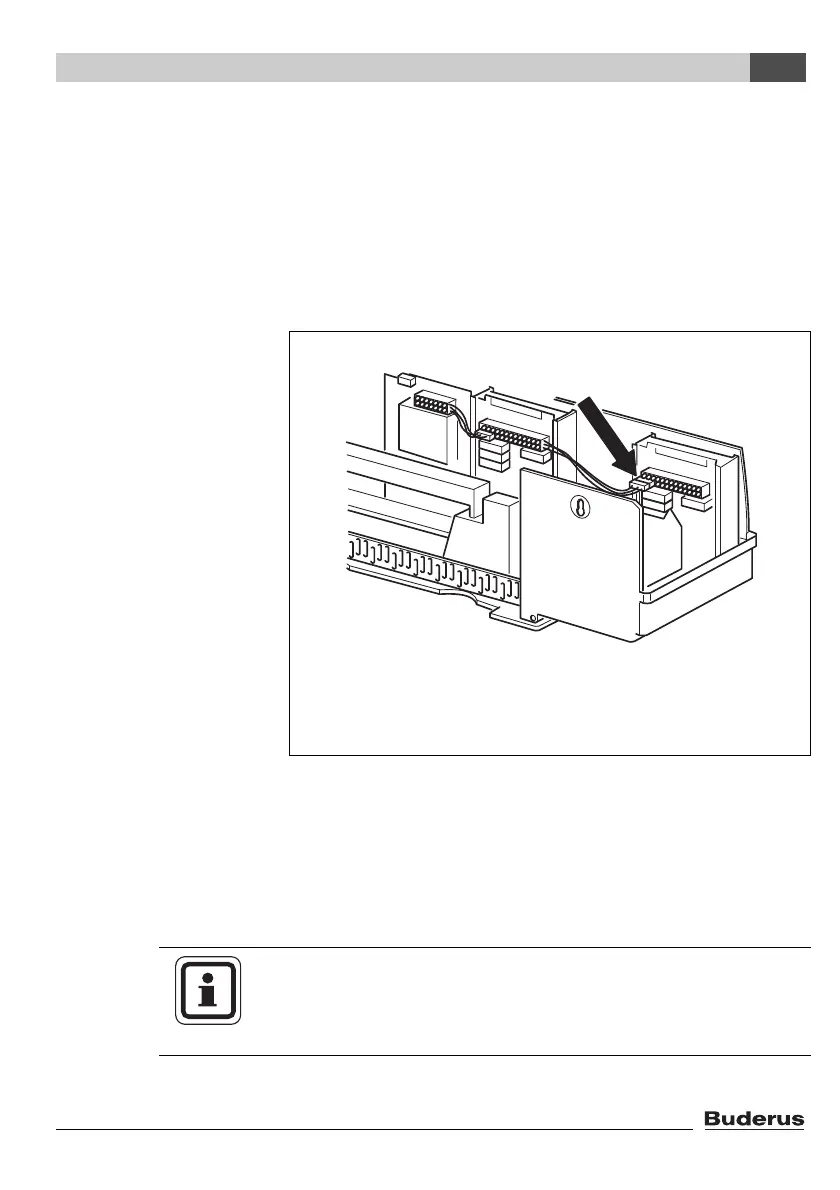
z Plug the 120 V module plug onto the position on the plug bar
(for module connection in slot 1,
Æ Fig. 5).
Fig. 5 Providing the 120 V power supply
USER NOTE
The connector clips are locked to prevent disconnection.
z When removing the terminals push the locking plate upwards.