4
Start up instructions
Logano G234X – 6 720 805 917 (2012/12)10
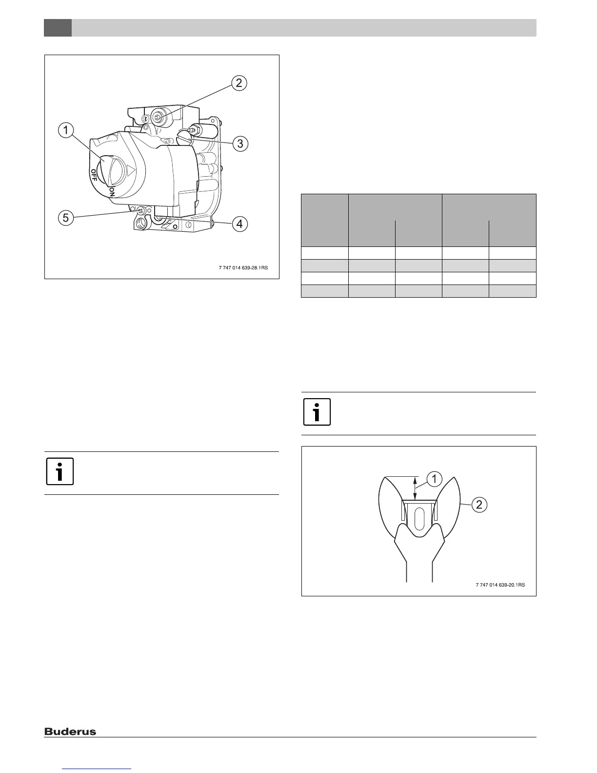
Fig. 11 Gas valve
[1] ON/OFF knob (in ON position)
[2] Screw plug for gas supply pressure test port
[3] Safety screw for orifice pressure setting
[4] Screw plug for orifice pressure test port
[5] Safety screw for pilot orifice pressure setting
If the main burner does not ignite:
▶ Close main gas shut-off.
▶ Disconnect heating system from the power supply.
▶ Notify the service department or gas supplier.
If the main burner has ignited:
▶ Using a leak detecting spray, check the gas fittings for leaks.
If no further leaks are found:
▶ Check the gas supply pressure while the boiler is operating.
▶ Record the measured values in the commissioning report (see
installation and maintenance instructions for the boiler).
If any leaks are found:
▶ Perform a leak test again ( Chapter 3.4, page 8).
▶ Wait five (5) minutes until all remaining gas has dissipated.
▶ Check whether there is still any smell of gas, including at floor level.
If there is a gas odor:
▶ Seal leaks.
▶ Repeat the leak test.
If you do not smell gas:
▶ Open main gas shut-off.
If boiler is equipped with an AquaSmart control unt:
▶ Switch on the power supply to the heating system ( Chapter 4.3,
page 9).
▶ Make sure that the room thermostat (optional) signals a heat
requirement (set thermostat at least 10 °F above room temperature).
▶ Check the ignition spark again ( Chapter 4.3.1, page 9)
4.3.2 Check orifice pressure
▶ Set the orifice pressure according to Tab. 5 while the boiler is
operating.
▶ Remove the safety screw for orifice pressure setting ( Fig. 11, [3],
page 10) from the gas valve.
▶ Turn the adjustment screw clockwise to increase the orifice pressure.
▶ Turn the adjustment screw counterclockwise to decrease the
pressure.
▶ Record the measured value in the commissioning report section of the
installation and maintenance instructions.
▶ Screw the safety screw for orifice pressure setting ( Fig. 11, [3],
page 10) back into the gas valve.
4.3.3 Checking the ignition flame setting
▶ Observe pilot flame through the inspection hole in the burner cover
( Fig. 10,[1], page 9).
▶ The flame must envelope the flame rod 1/2 to 1 1/2 Inches (15 to
40 mm) ( Fig. 12). If this is the case, continue with Chapter 4.3.4,
page 11.
Fig. 12 Correct pilot flame setting
[1] 1/2 to 1 1/2 Inches (12.7 to 38.1 mm)
[2] Pilot flame
If the ignition flame is too small or too large:
▶ Adjust orifice pressure for pilot orifice at the appropriate adjustment
screw.
▶ Remove the safety screw for pilot orifice pressure setting (Fig. 11,
[5], page 10).
The supply pressure for natural gas must be between 7"
and 10.5" W.C. (17.4 to 26.2 mbar) and between 11"
and 13" W.C. for propane gas (27.4 to 32.4 mbar).
G234X
Natural gas Propane
[inch W.C.] [mbar] [inch W.C.] [mbar]
38 3.0 7.6 10.6 26.5
45 4.1 10.4 10.5 26.2
55 4.6 11.5 10.3 25.8
64 4.4 10.9 10.3 25.9
Tab. 5 Orifice pressure
The adjustment screw for the pilot orifice pressure
setting is located behind the safety screw for the pilot
orifice pressure setting (Fig. 11, [5], page 10).

 Loading...