Do you have a question about the Buderus Logano G615 and is the answer not in the manual?
Explains warning symbols, signal words, and other icons used in the manual.
Provides critical safety warnings for emergencies, fuel leaks, gas, electric shock, and combustion air.
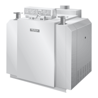
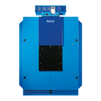
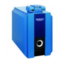
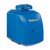
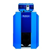
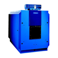
Details the intended purpose of the Logano G615 boiler for heating boiler water with various fuel types.
Outlines the Thermostream technology and required operating temperatures and pressures for optimal performance.
Lists applicable national and international standards, codes, and regulations for installation and operation.
Specifies extra installation rules for Massachusetts, including CO detectors and signage.
Illustrates the boiler's connections and provides key dimensions for installation planning.
Presents detailed technical data, including capacity, output, dimensions, and weights for various boiler models.
Lists components included when the boiler is delivered as a single, pre-assembled unit.
Lists components for boilers delivered in disassembled sections requiring on-site assembly.
Lists necessary tools and materials required for boiler assembly, not included in delivery.
Specifies required clearances around the boiler for installation, burner door opening, and maintenance.
Provides guidelines for installing the boiler on a base or foundation, including dimensions and leveling.
Details the process of assembling the boiler block from individual sections, emphasizing rear-to-front assembly.
Explains how to connect boiler sections, including preparing hubs, cleaning, and coating sealing faces.
Covers the process of setting up a pre-assembled boiler block, including safety precautions for lifting.
Guides the installation of the supply pipe and sensor wells into the boiler connections.
Explains how to insert the lower distribution tube elements into the boiler hub, referencing element length and number.
Outlines the procedure for conducting a leak test and repairing any discovered leaks in the boiler block.
Provides information on connecting the boiler to the piping system, emphasizing stress-free connections.
Covers installation steps for the draft diverter, baffles, and burner door assembly.
Details installing the boiler jacket and thermal insulation, matching parts to boiler size.
Details the installation of front, rear, and side profile rails onto the boiler assembly.
Covers the fitting of lower side profile rails, thermal insulation, and rectangular insulation.
Explains how to fit the vent pipe sealing collar and secure it with hose clamps.
Covers the installation of a flue gas temperature sensor, including welding a sleeve.
Details mounting the control panel onto the boiler, including alignment tabs and flexible hooks.
Instructions for hard-wiring the control panel to the building power supply, following standards.
Guides the mounting of the rear panel section and terminal cover onto the boiler frame.
Explains how to install temperature sensors (TRK, STB, FK) into their respective sensor wells.
Provides requirements for fill, make-up, and boiler water, including pH value and quantity limits.
Outlines steps for commissioning, such as establishing operating pressure and checking flue gas baffles.
Refers to separate documentation for starting up the Logamatic 4000 series control panel.
Directs users to follow the burner's technical documentation for initial start-up and to complete the commissioning log.
A checklist detailing commissioning operations, individual steps, and spaces for comments and signatures.
Explains how to shut down the heating system using the ON/OFF switch on the control panel.
Provides emergency procedures for disconnecting power and shutting off the fuel supply.
Offers information on maintenance contracts and availability of spare parts.
Explains the benefits of regular servicing for efficiency, safety, reliability, and environmental combustion.
Details the process for cleaning the boiler using brushes, including safety precautions and removing baffles.
Outlines the procedure for wet cleaning the boiler, including using cleaning agents and operating instructions.
Explains how to check the boiler's operating pressure using a temperature/pressure gauge.
Details the process of refilling boiler water and purging the system, including important notices about temperature stresses and water quality.
Provides templates for recording inspection and maintenance work, including dates and signatures.
Lists additional maintenance tasks that can be performed as needed, with references to relevant pages.
Introduces the spare parts list and groups them by component type, with page references.
Lists and illustrates front boiler block components and their order numbers.
Lists and illustrates rear boiler block components and their order numbers.
Lists and illustrates accessories for the boiler block, including flue gas baffles.
Lists and illustrates components related to the burner door assembly.
Lists and illustrates parts for fastening the boiler jacket and thermal insulation.
Lists and illustrates front and rear sheet metal parts for the boiler casing.
Illustrates the arrangement and lists sheet metal parts for side and cover panels for different boiler sizes.
Lists and illustrates sheet metal parts used as carriers for control panel components.
Provides forms for recording system installation, commissioning, and handover details to the user.