31
SERVICE (CONT.)
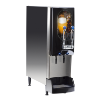
Dispense Valve
FIG. 26 DISPENSE VALVES
Location:
The Dispense Valves are located at the front of the
platform assembly. The associated flow adjustment in
the front of the still dispense valve is used to fine tune
the water flow to approximately 1.5 ounces per second.
Test Procedure:
1. Disconnect the dispenser from the power source.
2. With a voltmeter, check the voltage across the two
wire terminals of the valve solenoid. Connect the
dispenser to the power source. The indication must
be 24 volts dc.
3. Check coil resistance by disconnecting the wires
going to the coil. Place meter leads across coil
terminals, the meter display should show approxi-
mately 44.3 ohms +/_ 10% at 77°F temperature.
If readings are not as described, replace the valve.
Removal and Replacement:
1. Disconnect the two wires from the dispense
valve.
2. Remove the #6-32 screw and plate securing the
water manifold tube to the valve.
3. Loosen the two #6-32 screws securing the valve
to the platform assembly and remove the valve.
4. Install the new valve onto the platform and secure
with two #6-32 screws previously removed.
5. Inspect the o-ring on the manifold tube connector
for signs of wear and replace if necessary.
6. Connect the water manifold tube to the valve and
secure in place with the plate and #6-32 screw
previously removed.
7. Reconnect the two wires to each valve as shown
in Fig.s 27 and 28.
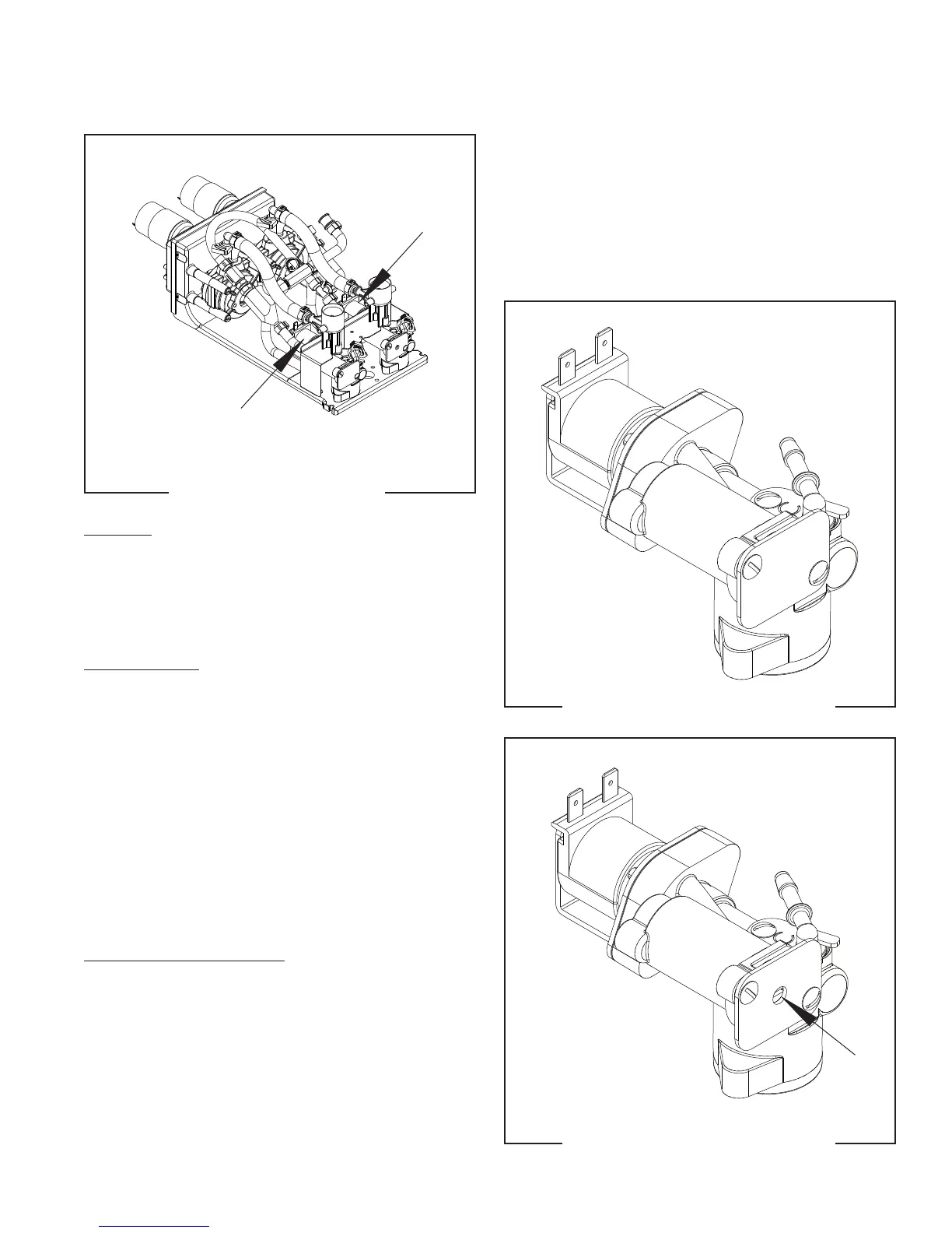
FIG. 28 STILL DISPENSE VALVE
FIG. 27 NITRO DISPENSE VALVE
Dispense Station #2 WHI/ORN
Dispense Station #1 WHI/VIO
YEL to Control Board
YEL to Control Board
Flow Adjustment
55124 021418